Wednesday 30 January 2013

Charge Bays (USB)

I was looking at the CBI Bezel, thinking about the big hole.  I don't want to charge R2 via a lead for the 12v battery, I intend to take it out to charge, but the 5v in the dome and the one in the body would be easier to charge internally.  So I had a bit of a ponder and decided to use 2 USB adaptor ports in the lower door to allow the 5v batteries to be charged, and use another in the CBI port to allow a phone or other USB device to be charged or powered from R2.  I may add a holder somewhere eventually too. :)


I think the lower one needs some details round the edges or sommat, i tried to mount them like the CBI but the alu had distorted and it looked really odd. But its functional and fills the door nicely. 

Then i did the CBI board, all blue LEDs and White for the side ones.  Need to do the leads and test it, but trust the force. ;)  Should be ok.


I actually decided to bolt the top USB in place.  I dont like glue.  :)  Then i also bolted the pan and CBI board together with a single bolt.  


Tuesday 29 January 2013

Leg rod and shoulder setup


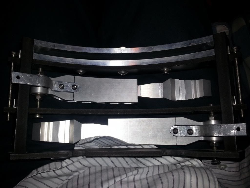
I was asked about the 2-3-2 shoulder/leg setup, i hadn't blogged it here so thought it worth a look.

My setup allows the legs to be removed, he couldnt be lifted or put in the car without this, but i liked the leg rod approach, so this is what i ended up with, the first lot of pohotos are old, i will add the updates at the bottom, the theory is the same its just been refined a little. :)

With the centre hubs removed (attached with magnets) 4 M6 hex head bolts go into the satelite brackets, and the wires are fed through the lower hole.  It allows for just enough movement for the 2-3-2 :)

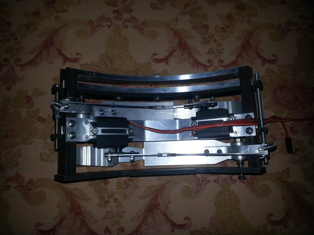
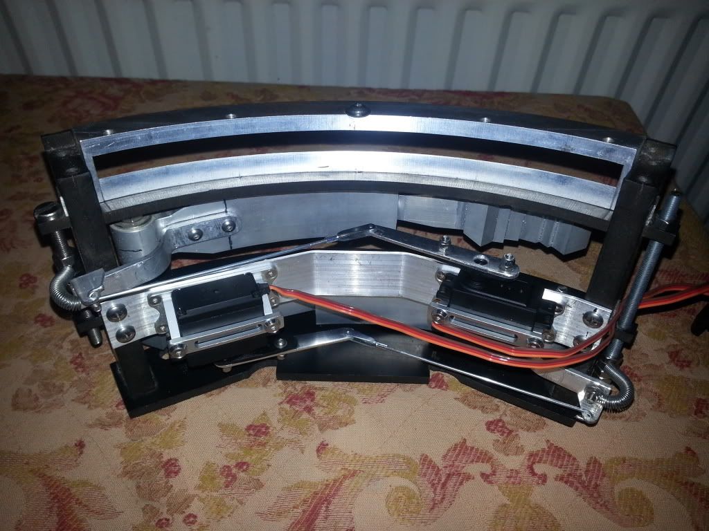
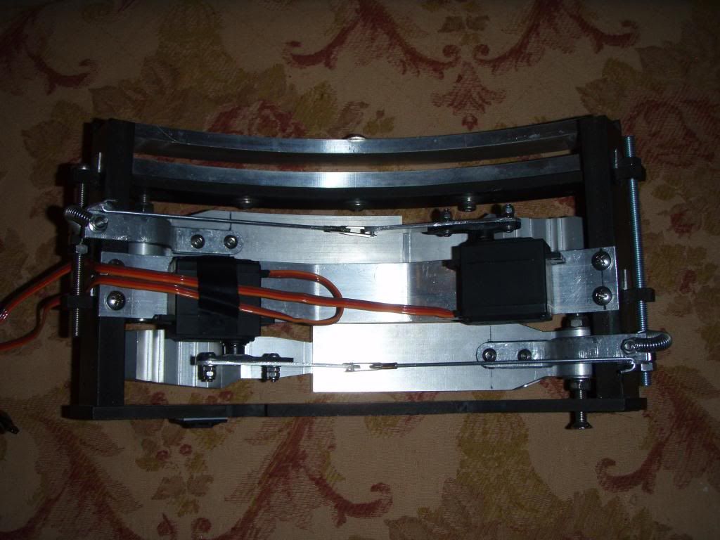
2 x 10mm studs go from a plate in the leg through the leg to body hubs into the satelite motor frames, the studs go through the alu frame and the 12mm plastic and that hole is backed by 2mm alu.  The stud plate is then stepped back inside the leg to body hubs and the leg rod is attached to run down the interior back surface of the leg.


Brackets have been lightened, shoulders reinforced and arms added to the brackets.  The arms hit plates in the frame in 3 leg mode, this was to help reduce the forces transferred into the actuators.


The hubs were cut to allow the studs room.


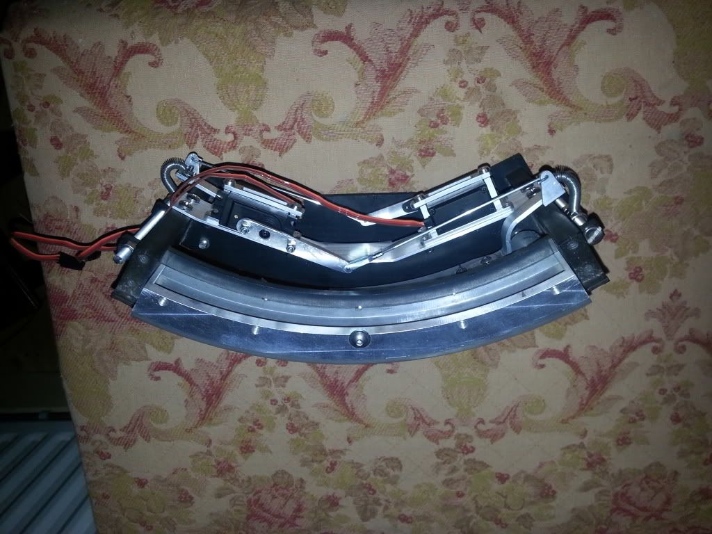
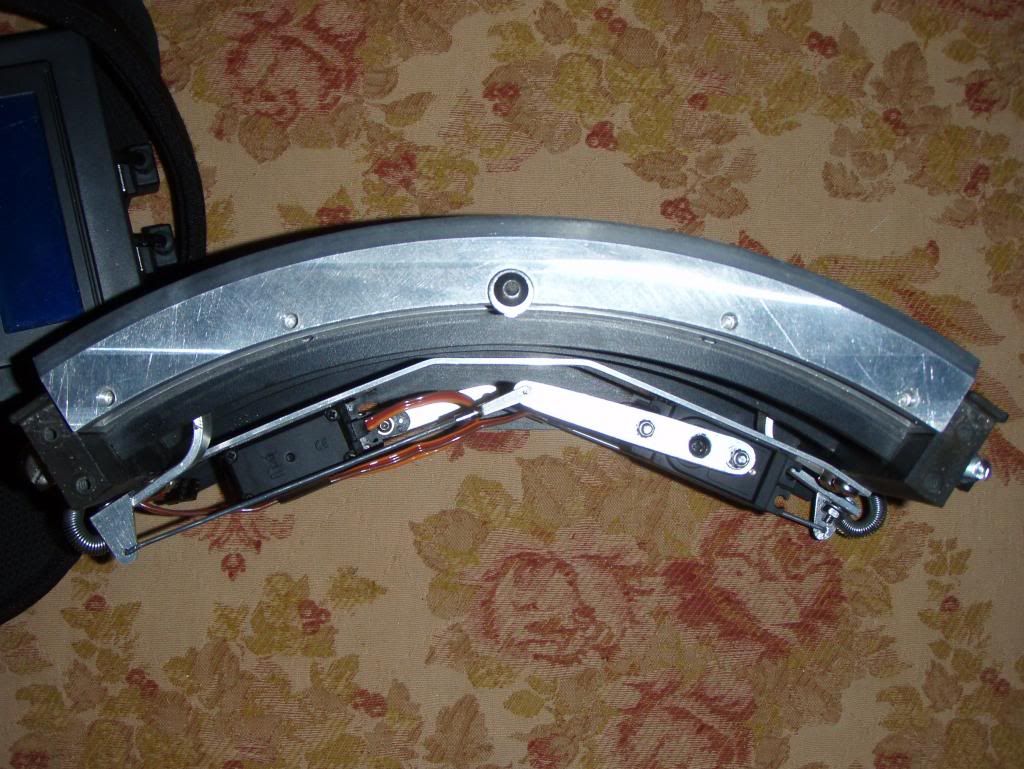
And the back of the Jag Leg was popped out.


You can see here how it all bolts up.


May as well add the Hub mount here too while im at it.  You twist it to release one magnet and then it can be removed, with both on the steel it's going nowhere. :)


It all fits, but the shoulder hubs sit approx 1mm proud.


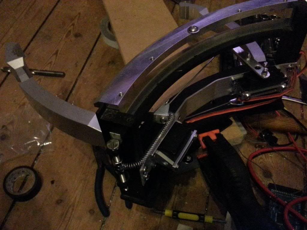
The leg rods are bent in a slight step in the leg, to allow it to exit at the right spot to align with the u-channel of the foot, but inside the foot.


I went for a 20mm top and 40mm bottom offset, and my control rods are bent in the leg to step up to the exit hole, this avoids the bolts.

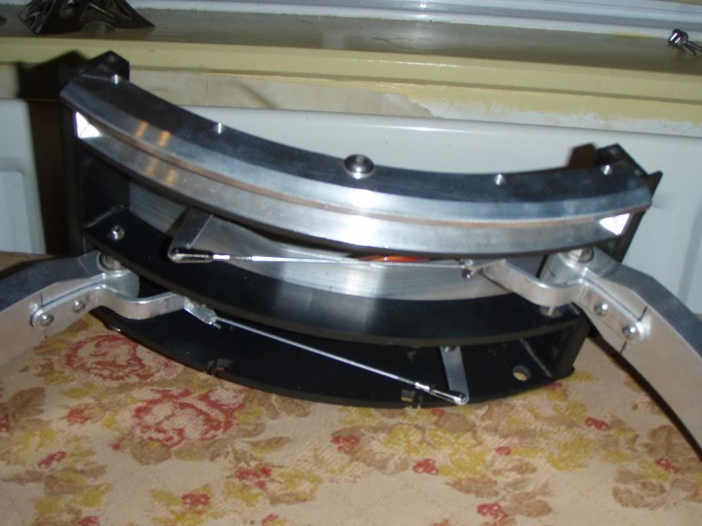
The rods are stainless steel, this was to help avoid the attraction of magnets in the back of the hubs.  So that was the first draft and concept proved, but it needed work, more to come too.

Mike Bentley kindly had some nice little brass bits made, they have an M4 thread all the way through, the feet and rod, or shoulder plate and rod slip over the brass and it acts like a bearing withthe help of an M4 nut and bolt and a few washers.  That made a BIG difference, but still had a bit of play.

So I then went back and added bearings to the hinge point in the centre of the mech. 2 6mm id flange bearings and it was a lot firmer.


But it still had my home made studs, rubbish, they kept coming lose.  So James took up the challenge and redid the studs for me.  Beautiful.  :)


Next job is to redo the mounts for the actuators, both top and bottom, take out all the play there.  Then i need to redo the code, all the balance points have changed thanks to the firm up and the battery install.  So i will wait and redo the timings once i have the skins on.


5 years of building & body pans


Checked a few dates today.  Turns out that my first part to be ordered (added to the run list) was my dome, and that was paid for on 30/1/2008.  So tomorrow is officially my 5 year anniversary of the first real commitment to make an R2 unit.  I didn't really start building till Oct 08, but building is like being the Queen, 2 official birthdays and many more parties. :)  I had thought that it was a year earlier, so I don’t feel like such a slow lazy slob for taking 4 ½ years, 5 ½ was too slow ;)

I have been working on the body pans this week.  Flip kindly let me use his break a while back, so I had a few sheets of 1mm alu bent to shape and ready to go, so I trimmed up the insert I had made for my previous attempt at the big door pan, and James’ lovely CBI plate was trimmed to suit the bent bit and I got both sides roughed out.  I then cut holes for the hinge access and hey presto instant pans. :)  The dremel was amazing on 1mm alu, so easy to use and great results, I couldn't have cut the delicate bits with the saw without bending the alu.  To finish these off I just need to add angle to use as a bracket for each. 


So door servos for these and the CBI board and code and we are almost ready for the skins. :)  I might look at adding a USB output or 2 in the small lower door, for connecting up phones etc for recharging, will have to see how they fit. :)

Wednesday 23 January 2013

Utility Arm Setup Complete

Finally finished the Utility arms.  They need to be stripped and polished up, but the construction is done. :)

I replaced the springs with smaller diameter ones, this made the pull back action at the end of the travel a little firmer.  But the tape gave out on the servos pretty quickly. :)  So i hopped on eBay and grabbed a couple of alu servo brackets.  They arrived today, so I cracked on and mounted them, set it all up again, found the open and close points and got it working.

Held steady it's great, so I need to mount it for best results, but it works great, the servos cope with the springs with no issue at all, apart form the difference in open v close speed, but I might be able to sort that via the Arduino.  I am not sure on the current drawn to keep them open, I may need to measure that, but I am using a 10A 5v supply to make sure.


So on to the door servos and pans.  Cant wait to get these under pad control.  I think these might have to be up and down on the D pad, my first non trigger commands. :)  Well if you don't include start and select, they have stuff already, but the first big button. :D

Sunday 13 January 2013

Pad Changes and Xbee Shields

Mainly because James couldn't wait :) I had to make a decision about the Arduino to use in the pad end.  I had wanted to use a mini mega, but it was going to be a bit of a pain to get working.  Then looking at what I had I decided it wasn't that far off fitting.

So I started by redoing the screen mount so that it sticks out giving more room in the box, then I made up a shield to do all the wiring instead of using connector blocks and the explorer board for the Xbee   Luckily it all fits, so I now have a standard mega running the pad end and as my code is almost too big for the 32K chips already it will allow growth too.


I also tracked down the Pad crashing.  It is the PS2 library, something to do with the trigger buttons, but I found if I do R2+Triangle, then Triangle after boot up then the pad runs without crashing no matter what I do.  I think it's the way it allocates memory.

I had been asked several times about what I am using.  So I have started to document it.  Below are the main droid and pad shields.  The Droid one connects to all the slave Arduino via I2C, so the MP3, Dome Servo, Teeces etc all have their own set-ups.  These shouldn't change much.  The extra stuff is done via the slaves and the code.

I don't recommend doing this unless you are willing to learn some Arduino code, it isn't perfect and I am still working on it, so while I will try and help where I can, if its something I haven't yet finished you will have to wait, and I took a while to get mine working flawlessly so please check your wiring with a meter and make sure wiring isn't the issue.  99% of the problems are wiring, it needs to be perfect.  Once mine is done i hope to rejig the code to make it a little more user friendly. :)


So to get started the BOM would be:

1 x New PS2 Wired Pad (don't bother using an old one, its tricky enough when you know it should be good)
1 x I2C 20x4 LDC Screen - Ebay
2 x XBees, I used the XBee Pro 60mW Chip Antenna
2 x XBee Arduino shields
1 Arduino Mega for Pad end
1 Arduino Uno for Droid Master
1 x 5200mAh 5v Power Bank Battery to drive Pad
2 x 90 degree USB leads to run from battery into pad
1 x 90 degree plastic bracket, the ones i used came on a packing crate to protect the contents from the plastic straps.
1 x Plastic box to fit Mega and shield, i got mine from Ebay.
2 x 2.7K I2C Pull Up Resistors
1 x 10K PS2 Data Line Pull Up Resistor
Solid core wire and header pins to wire up shields.
Crimp terminals, blocks and wires for all patch leads.
1 x Sabertooth 2x25
1 x Syren 10
Optional Round soft pot for dome position control and wiper.


Saturday 12 January 2013

Utility Arm Servo Setup

I have been having a lazy phase with R2 recently, think i used up my concentration before MEM. :)

But finally finished the utility arms setup tonight.  I had a few factors limiting me here, I had an A&A arm carrier that covered the sides of the arms, and my dome motor is mounted just behind the arms.  So I had started by adding arms to the back of the utility arms and went from there:


I got some 15KG standard size servos and added a longer arm one, then using a threaded servo rod and a cleat i connected it to the arm.  The first draft of the mech looked ok, but in the full open position could be opened too far and would then not close.  Also the servo mount had too much play.


So I added an alu flat bar bent to shape across the carrier to mount the servos to, it also really helped reinforce it all.  I just added the servos using strong 3M thick double sided tape, they seem really strong, but I can add brackets later if needed. Then I had a mess about with a few springs, and after trying a few spots and sizes I found the magic combo and it now works like a charm.  The servos take quite a bit more current when open thanks to the springs, so it wont run from the Arduino directly and i cant find my crimps to hook up my 50W 5v converter, so will have to wait to test the two together.  But the servo is fine with the spring, it just resets the Arduino. :)  I then shaped and tidied all the bits, did the other arm too and replaced the hardware on one side of the carrier to make a spring mount for the lower arm, and job done. :)


The servo arms do stick out a little when open, but I quite like that.  It fits in front of the dome motor really nicely. :)   Will post a video when I can find those crimps.

Body pans and door servos and I'm ready to do the skins.  After polishing the right bits. :)  And maybe CBI first too. :)