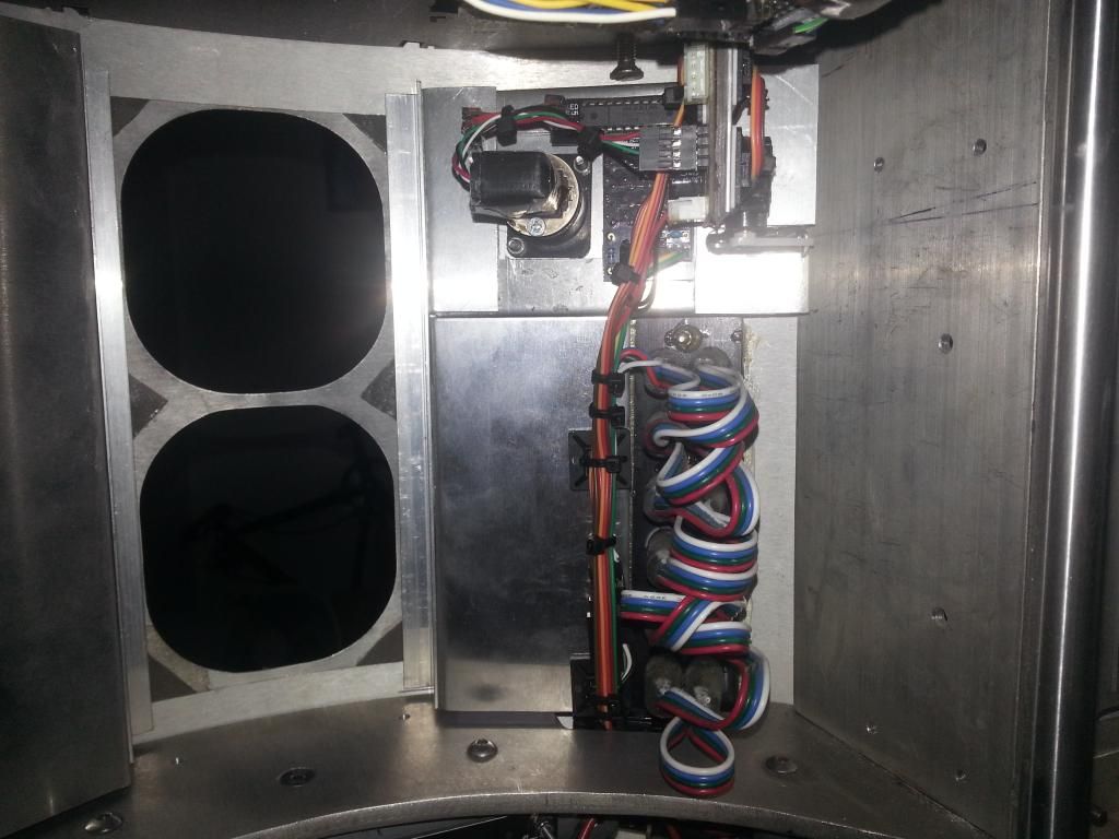
I spent last weekend rewiring the body. 4 of the door servos attached to the skins no problems, but the CBI didn't have the space around it, so i was forced to mount that one to the back of the CBI pan.
When the base was done, i offered up the skins to the frame and found that i would need to cut a lot of the frame to fit it. So after a bit of a ponder i decided to move the long door servos to the top of the hinges so that the frame wouldn't need as much adjustment.
If i were starting fresh, i think that with the right arm carrier one could fit all 5 servos to the skins, with the long doors and the big door and CBI servos above the doors, and only the small door below, then the frame would only need one cut out and would be a really neat setup.
So with the body rewired again i marked and cut the frame to accommodate the other servos, and the front skins were again able to be fitted. I also cut access to the master Arduino port. :)
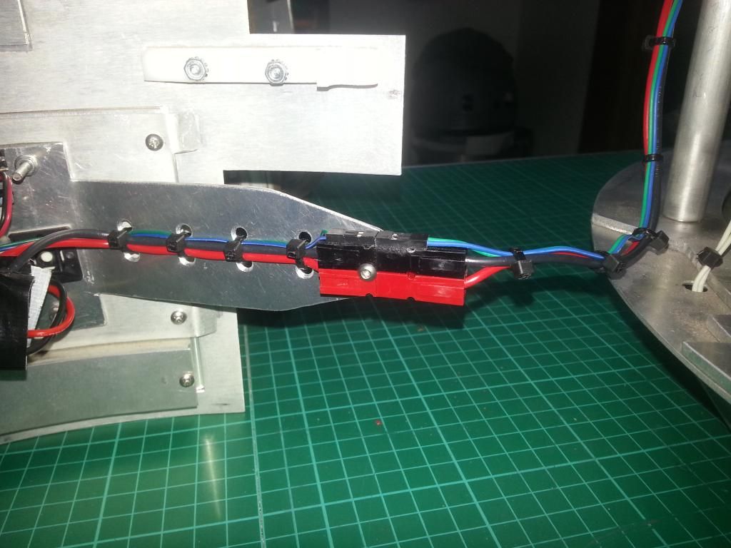
That left the wiring connections. So after a lot of thought, i added an arm to the back of the pocket vent, then glued a 2 pin servo type lead to the top of an Anderson connector and hey presto, one connection for all 4 wires. :D That is accessed via the back when the front skins are fitted, or can be pulled out for off droid testing, i even made up an extension to allow it to be used more easily when the legs are on.
So all was looking good, by Sunday morning i was ready to test. This new setup allows the body to be tested off droid, so servo testing was easy. But the 8A UBEC cant cope with the Utility arm servos, especially when run with the springs.
While testing the servos i tried the servos on 6v, and they are SO much nicer, more solid, quieter and faster. So i looked about and found myself a 15A variable buck stepdown, i will run the body servos at 6v. I have disabled the arms for now, and have finished the rest, but will redo the servo supply when it arrives.
But mid Sunday i wasn't feeling well so decided to stop for a bit. 3 days later i was still in bed and couldn't face R2, so i decided to wait for the weekend.
When the weekend arrived, i recoded the body code to added the changes to the layout and add servo positions, and started testing. A couple of wiring issues later i had the door servos, CBI, Vegas kit and charge port working well.
The body unit still needs a little TLC, but i ran out of cable ties, and i need that stepdown, so i will finish that off when i can complete it.
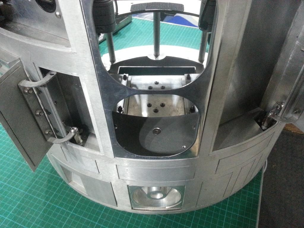
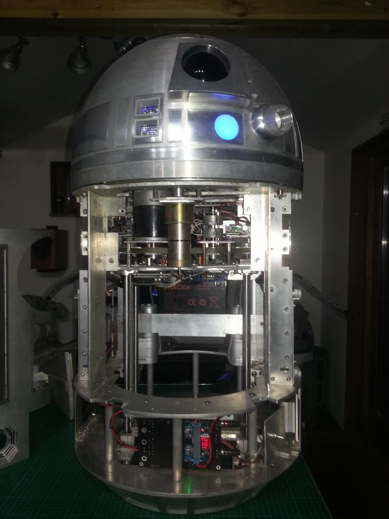
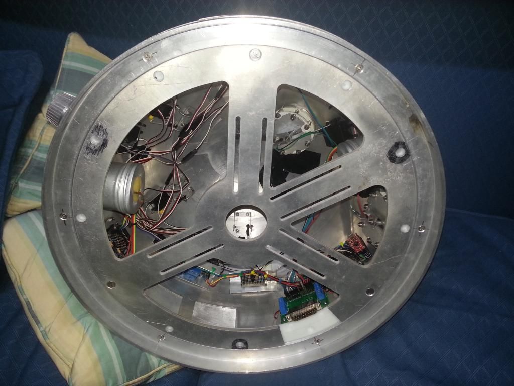
The frame looks so empty! Really pleased with progress. The droid is now much easier to run, with the dome and body being standalone testable units. Id like to make the master unit removable, and improve MP3 and 2-3-2 disconnects from that, but that can wait for now.
While doing all this, it has made me think about the Vegas kit, it is a great effect, but the cheap kits arent great, the wiring and voulme used is rubbish. So ive been looking about, i can fit 33 Neopixels in the LDP and redo the Coinslots too, all to be low profile and neat and tidy. Just the cost and removing the glue from my current setup. :( Will save that for next year, and when i do droid 2 i will redo both kits.
But it has left me thinking. All 3 legs could be better and easier to remove. I am going to do a similar thing to Flipside and add a quick release to the Centre leg, that can be a Christmas job. But im having trouble thinking of a suitable method for the outer leg release, they need to be so solid. :( But i do have a plan to do away with the need to strip as much of the leg and allow the wires to connect automatically, so maybe better but not perfect.
I now have room for all the dome and body gadgets, and space for my docking screen. It is a great step forward and will make future mods a lot easier.
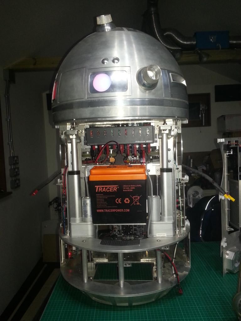
More steady progress. The droid, all apart from 2-3-2 was totally stripped of all electronics. With the aim to look at it all a fresh and try to make it easier to use, less likely to shake stuff loose and to use spaces that are currently wasted, freeing up space for more future goodness.
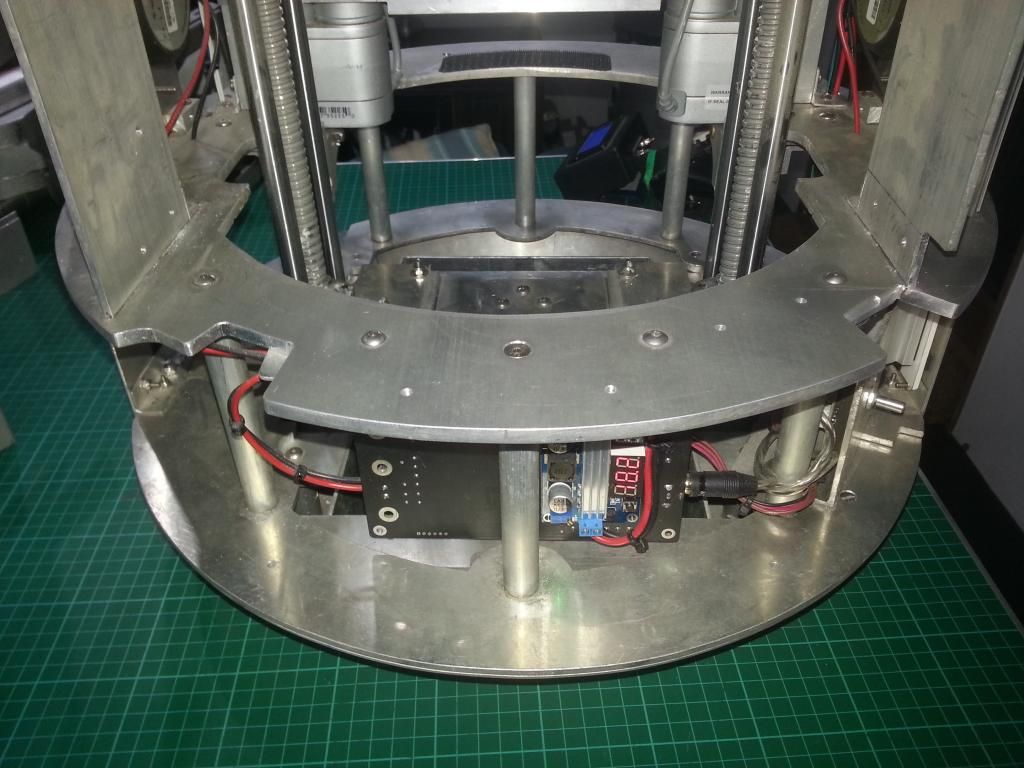
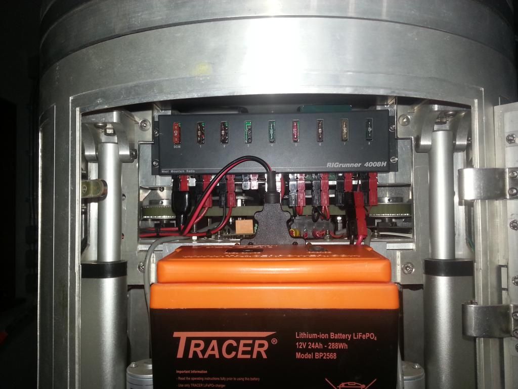
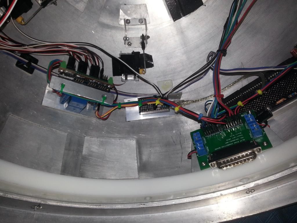
I have wired up a panel that will mount to and behind the Rigrunner. This attaches to the top ring of the frame and holds:
Rigrunner
Master Arduino with Xbee shield
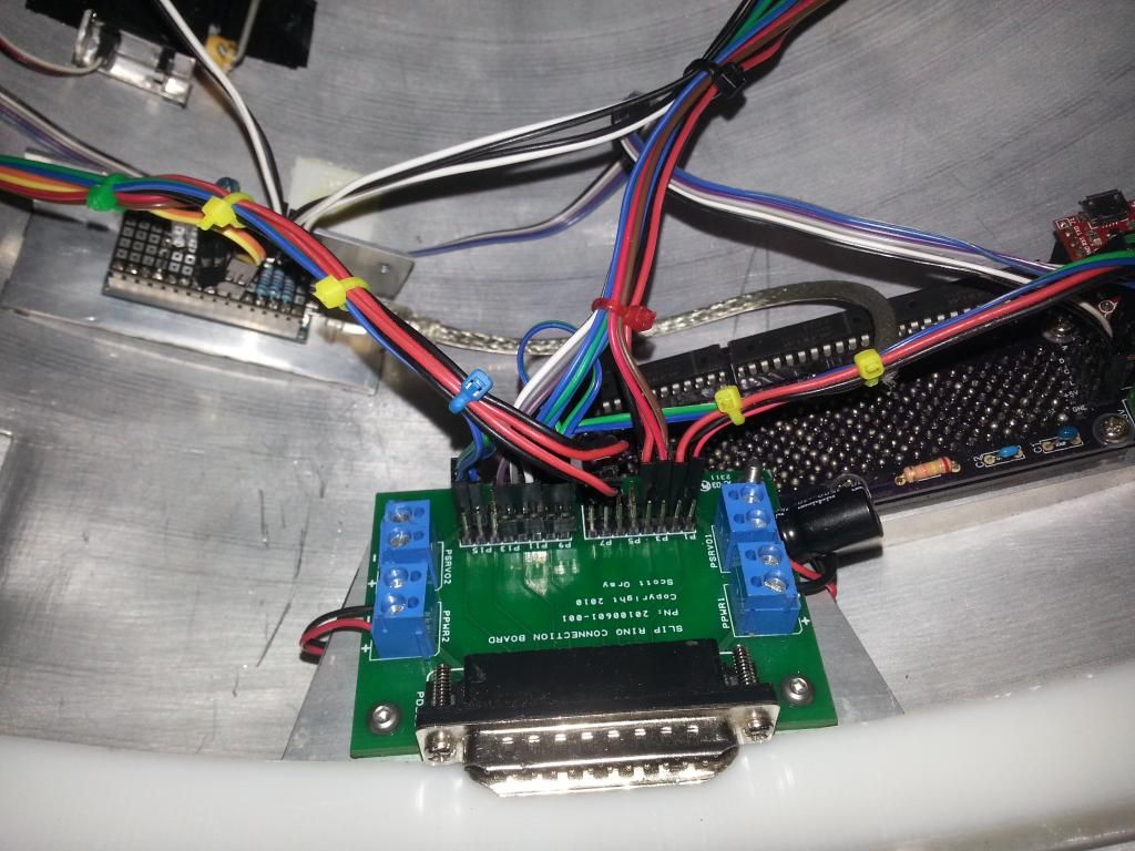
Slip ring and connector board (Acting as I2C and 5v Bus for Master, 232 and MP3 Arduino)
UBEC for board 5v supply
Feet and Dome ESC
Relays for Dome and Feet
Dome Motor
It all fits great but it is more difficult to access, unless i remove the top ring. I may revisit the access at a later date depending on the needs. The good thing about this approach is that i can test it as a standalone unit, making sure the dome motor and the relays are under control, then add the dome and debug that, and then add the remaining units as required.
Then I returned to the dome and finished off all the cable ties and neatened it all up. I'm really pleased, it is the best that the dome has been. Really neat and tidy. More than 70 cable ties for 1 dome! I thought I was reducing the weight, not increasing it! :D
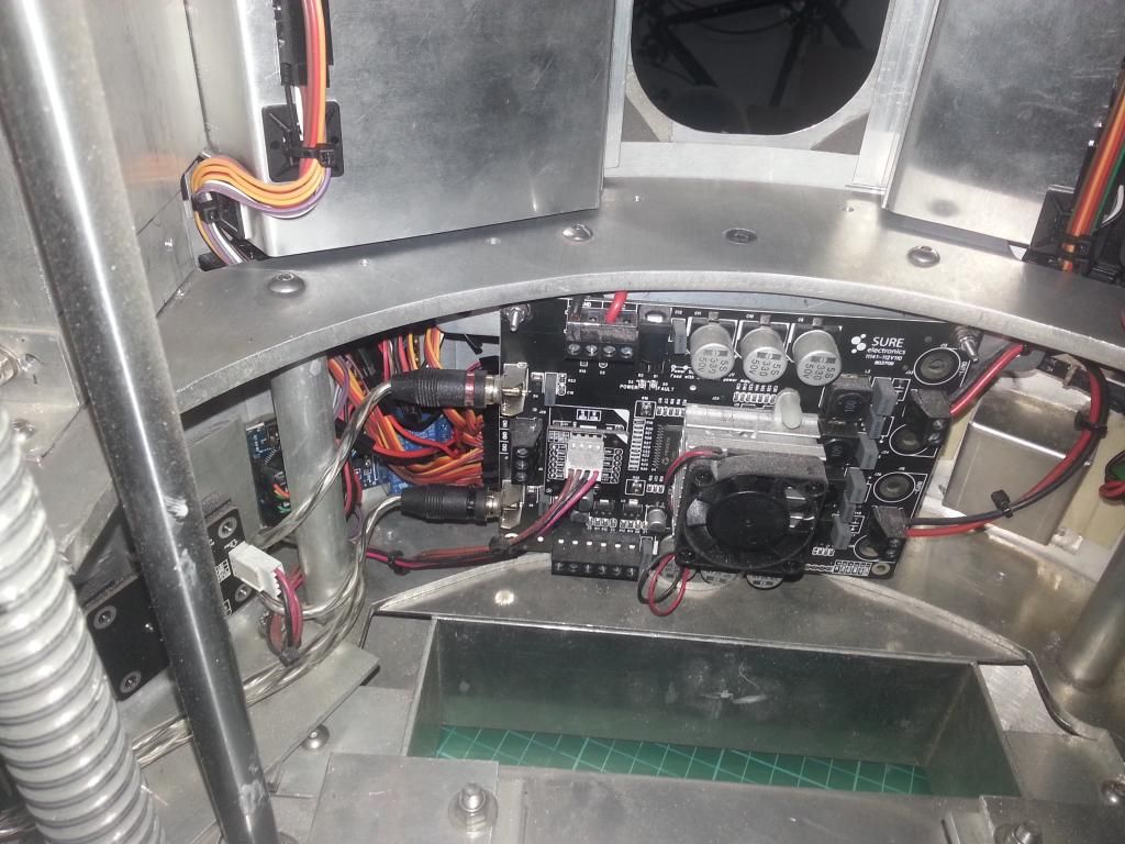
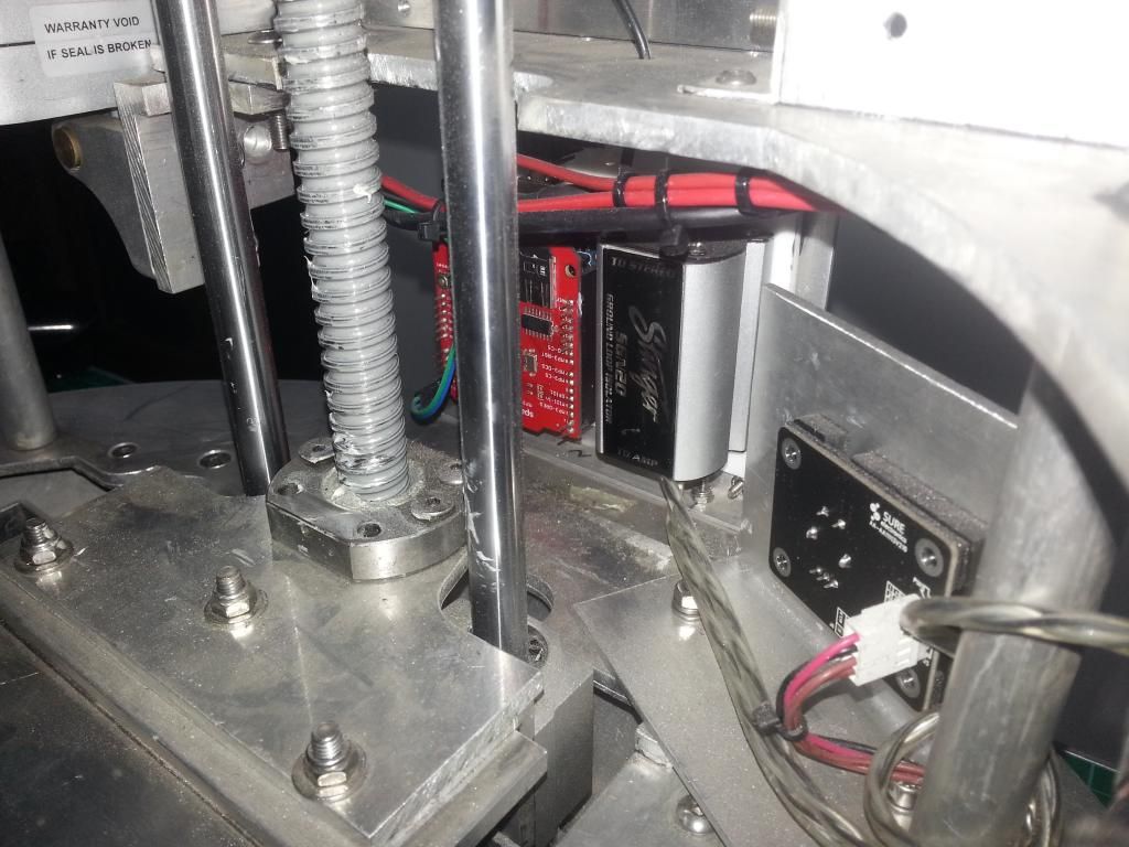
Next up was the audio elements. The MP3 shield has a 3.5mm stereo jack, this connects to the Ground loop isolator that uses dual RCA connections. I was using a 30cm adaptor lead. But i had a thought the other night, got on-line and found a right angle 3.5mm stereo jack. When that arrived i cut the GLI wiring back, added some heat shrink and wired it up to remove all the unnecessary wiring and really neaten it up. Very pleased with that little change, it has removed a lot of unnecessary material, and it is shiny. :D The MP3 Arduino and Shield and the GLI have been mounted to a small styrene board and will be moved to sit behind the right side panel. It was dead space, but using it for this will free up the front for gadgets etc.
Then i added the new variable step up converter in-line on the supply to the amp, and mounted it to the back of the Amp PCB. I should now be able to up the voltage as required.
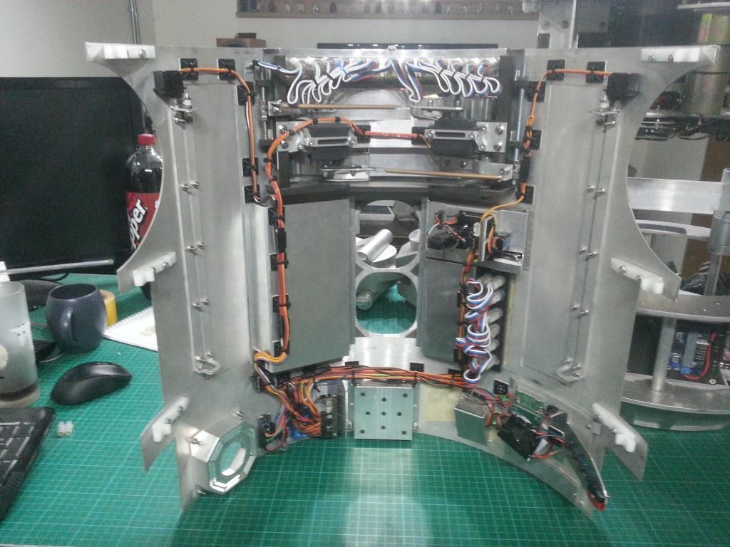
Then the body. This was becoming a problem, the more i changed the more problems i could see. I kept coming back to the idea of mounting everything onto the skins to allow it to all be tested off droid, and to neaten all the wiring, and also get rid of those servo rods. Eventually the front skins will have just 4 wires and everything mounted to the skins, only connections for 12v and GND and the 2 I2C lines are needed, im intending to mount Anderson connectors to the skinsnaps, so it should just click on and off. :D
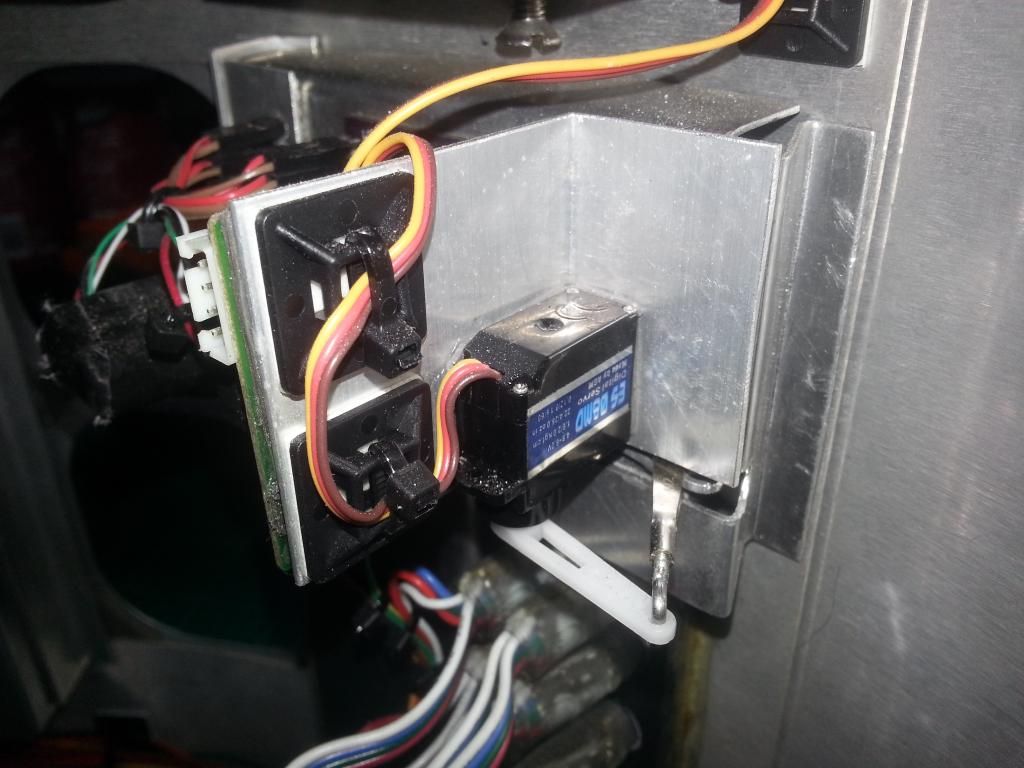
I decided i was too far in to turn back and cut corners now. So first up was how to mount pans to the skins and the servos for the doors.
I had the perfect T extrusion, i cut it to length and bent the pans to fit, making new bits from 1mm sheet where needed. Then just used trim tape to fix it into position, should be sound. The hinges with the 2nd hole cut off can work inside the pan, so the pans can be solid. :D I hope it works. :D I bodged the pans for now, more ali is ordered and i will redo them before final fit.
Turns out that a std micro servo fits with an almost identical pivot to the JAG hinges if mount directly onto the skins. From there a simple offset to the hinge will connect them beautifully. They will have to be glued in, but they should be sweet. That will be fine for 4 of them, but space on the CBI door is tight, so that will be a different setup. I only had one for messing about with, so jumped on ebay and ordered 5 metal geared high torque ones, but of very similar dimensions. Fingers crossed they are delivered ASAP.
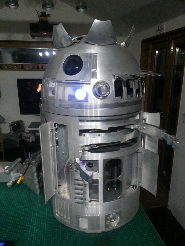
The body will look so empty when the skins aren't mounted. :( But I'm really pleased with the touches that seem to be working out. The dome attachment connector is brilliant. One of my best ideas so far, and if I can sort the master panel removal, that will be brilliant too. It feels like i am taking it from base prototype to a more complete version.
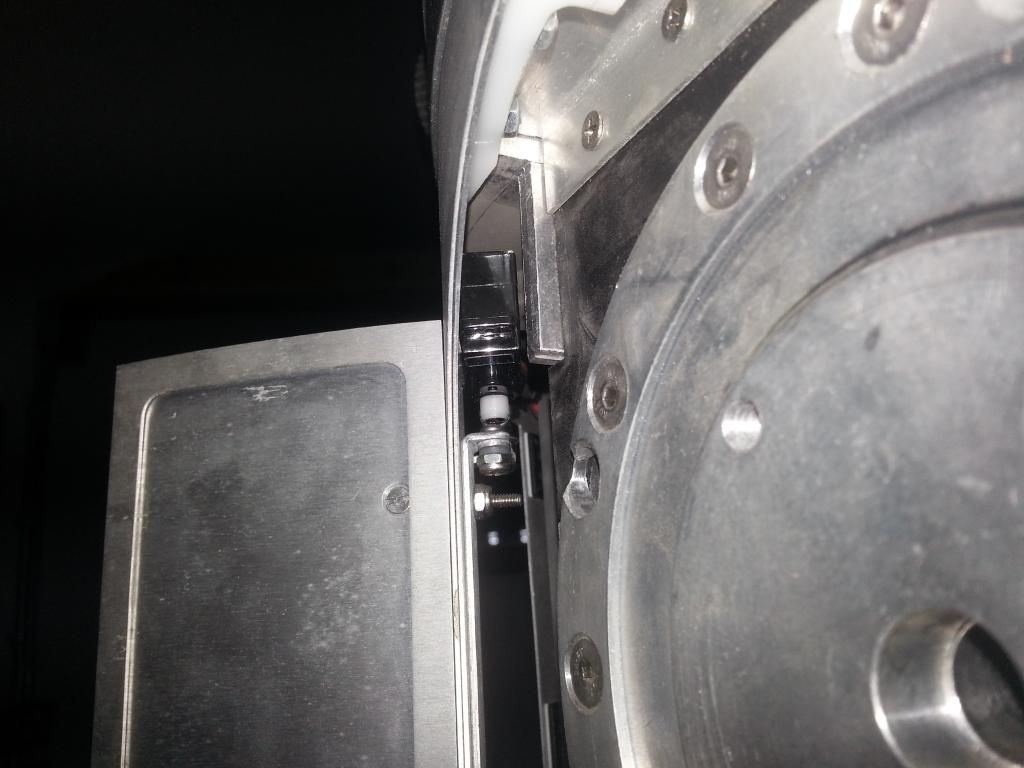
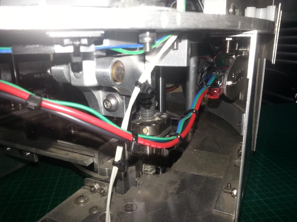
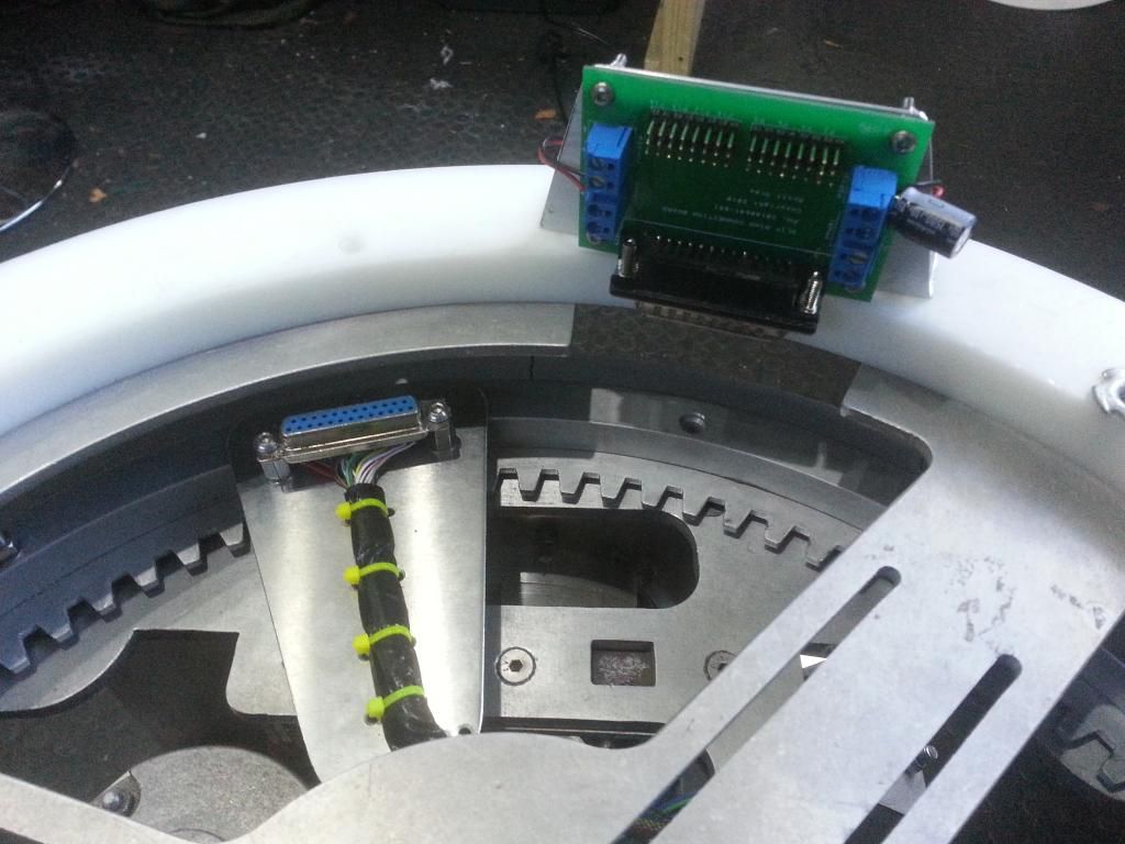
I saw a great droid at FACTs that had 2 serial connectors (9 pin i think), on a dome cross member. These dropped into the females on the rockler. This had 2 main advantages. Obviously you dont need to connect the slipring by hand, but 2nd was that the dome location is set so the wiring can be better controlled.
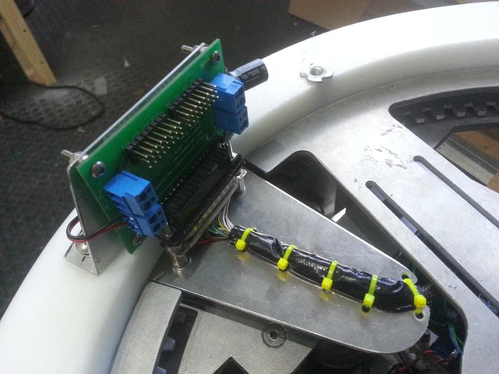
So i had a look at my setup while i had him apart again. After a bit of a think, and a play with a template to find the sizing and position, i decided to go for it. I cut a small section from the dome baseplate, to allow a fixed point to be added to the rockler. Then made an arm to carry the slip ring wire and keep it well positioned, i then fixed this to the rockler Next i used some M4 hardware to mount the Slip ring end of the serial port connection to the arm, ready to take the PCB.
This seemed sweet, the PCB would just sit on the Derlin ring, but the connection was stiff and wouldn't quite sit right. So removed the male surround from the pcb side and opened it up as best i could, then removed some of the side material to clear the M4 button heads and opened it a little more. Eventually the PCB would slip on and off with minimal force, and sat tight to the connector.
Then made an Ali bracket and mounted the PCB properly to the Derlin ring. It works really well, with the actual dome on it drops on really easily, the 3 long studs align the dome, and the arm slots in to the hole in the baseplate and connects the dome to the body.
This is going to make a big difference to the running of the droid.
While i was doing that bit it seemed logical to rewire the UBEC. To keep it neat and simple, i removed the metre and switch. Then had a look at the wiring for the Adafruit, Relays and Servo/HP Arduino. Im pretty chuffed with the results so far. I have run out of cable ties, so will have to finish another time. But it is a much nicer looking set-up for the changes so far. I just hope it works, it is almost what was wired up last time, so should be ok,
I will glue the dome to the ring eventually, but will do the lifters and stuff first, so gaffa tape will hold it, on just in case, for now.
The battery was posted to Deban on Tuesday and is already on it's way back to me after it's check up. :) Great customer service. I also ordered a couple more T-Bars, i think mine is dodgy, and id like to be able to use the battery in either droid when Droid 2 gets a look in.
Body is still in bits, but i have a few plans for that too and im waiting for components. But MP3 and GLI are moved and will be rewired. Body unit wiring will need consideration, but im hoping to make things more accessible and use some dead space while freeing up more room for the gadgets.
James via a chat with Roger mentioned a new concept for connecting the legs, if that works this will be a very different droid to take apart and assemble. Deffo looking in to that one, real potential and not seen it done before.
Still cant quite believe im redoing and undoing a lot of the work i had just finished. But it is all in the name of a better droid long term and testing a few more concepts and set-ups. Too late to turn back now.