I have been busy, but not on Pic worthy stuff. But it has been so long since the last update it needed something to prove I'm still here.
I have started on another droid. :) Partly to follow the BHD write up and improve it as I go. This weekend should be the first complete bench run for the new setup. :) This droid will be a collaborative effort and so will be blogged elsewhere. But it is a truly exciting project with some really cool engineering challenges. I will link to the new blog once we get going properly. This droid will hopefully be a more practical droid, we are aiming for under 40Kg total, and it will be a truly unique droid, hopefully its abilities will be a little bit special. That should be rolling by the end of Feb, with improvements to follow after that.
So the write up is getting there, the shields are neater and easier to make now, i have been getting feedback from others too, and it is all looking good.
I am also working with Felix on an Anglo/German BHD pad upgrade. This may be in phases, but should be smaller, lighter and neater at the pad end, and we might have to look at a droid master PCB too. Its looking good so far.
My current R2 isn't getting too much time at the moment, but i have ordered JoyMonkey's new logics, and also have one of Felix's superb 2-3-2 controller boards, this will make the electronics element of the 2-3-2 much smaller and neater, but its a huge job, so may have to wait a while before I fit it. I may wait till the other droid is available for use, at least then I will have one in use and one in the pits. :) I have so many things i want to do to it. I still need to fit the Master Utility arms. :)

Friday, 10 January 2014

Friday, 6 December 2013
BC Member! Me!
Well, i have exciting news. I am on the BC. :D
Really hoping i can contribute. The club has given me so much, i would be honoured to give a little back.
So i suppose this makes me BC approved. :P Hope it can also help the UK club go on to even bigger and better things, i am proud to be part of the UK club and know we can go from strength to strength.
Really hoping i can contribute. The club has given me so much, i would be honoured to give a little back.
So i suppose this makes me BC approved. :P Hope it can also help the UK club go on to even bigger and better things, i am proud to be part of the UK club and know we can go from strength to strength.
Monday, 2 December 2013
BHD 2.0
Easy Dudes.
I have been a busy boy. :) The wiring of the control Arduino shields has been redone. The pad now uses 2 way serial, opening up many more options for the future. Also the I2C now transmits more than the script number, it also transmits the charge level. So one reading taken on the master is passed to all the end units. :)
I redid all the end units and spent a but of time making it work as reliably as before. It took a bit of playing, but its great. :) I have a load more coding to do now to make the most of the extra functionality, but it all works and the wiring is set.
He spent a couple of hours with the Scouts in Harwell on Wednesday, and they all had a go driving, so he was VERY thoroughly tested. There was some serious button bashing going on and he didnt miss a trick. :)
The new Leia and Luke messages are LOADS louder and now work with the R2 sounds really well.
Latest Code and Files
While redoing the code and testing i tried to document the setup. I have a BHD write up now. But i want to run it myself for a few more events and also follow it to wire up a 2nd droid to help improve it. I will be starting that this weekend. :) Maybe try and take a few step by step shots to help simplify a few bits.
I will post it about when finished and fully tested. :)
So the blog is now back on-line and all the Google Drive files have been tidied up. :)
I have been a busy boy. :) The wiring of the control Arduino shields has been redone. The pad now uses 2 way serial, opening up many more options for the future. Also the I2C now transmits more than the script number, it also transmits the charge level. So one reading taken on the master is passed to all the end units. :)
I redid all the end units and spent a but of time making it work as reliably as before. It took a bit of playing, but its great. :) I have a load more coding to do now to make the most of the extra functionality, but it all works and the wiring is set.
He spent a couple of hours with the Scouts in Harwell on Wednesday, and they all had a go driving, so he was VERY thoroughly tested. There was some serious button bashing going on and he didnt miss a trick. :)
The new Leia and Luke messages are LOADS louder and now work with the R2 sounds really well.
Latest Code and Files
While redoing the code and testing i tried to document the setup. I have a BHD write up now. But i want to run it myself for a few more events and also follow it to wire up a 2nd droid to help improve it. I will be starting that this weekend. :) Maybe try and take a few step by step shots to help simplify a few bits.
I will post it about when finished and fully tested. :)
So the blog is now back on-line and all the Google Drive files have been tidied up. :)
Monday, 7 October 2013
BHD Logo
Was messing about last week, and decided if writing it all up, the BHD needed a logo, or something recognizable to go on paperwork, PCBs and maybe even stickers/paches. :)
Here it is:


Here it is:

Didnt think about the intel inside thing. :D

2-3-2, Dome Servos and Arduino Workshop
Building has been fun recently.
Decided to delay the magic panel and DBC installs, I want to look at the
base of my code first. Reduce a few signal lines and replace them
with 2 way comms.
But I added the 2 relays to the dome, these control the power to
the servos. One for the 3 HP servos and
one for the rest of the doors. They both
prevent any servo twitch as the main power is connected, so connection order is
no longer an issue for the dome. They
also power off the door servos 2s after they are all closed. This allows the doors to be pulled open when on, stops any servo buzz
and saves power. Really good, highly recommended. These will be included in the BHD write-up. Will also be adding these to the body servos,
and maybe the dome motor for completeness.
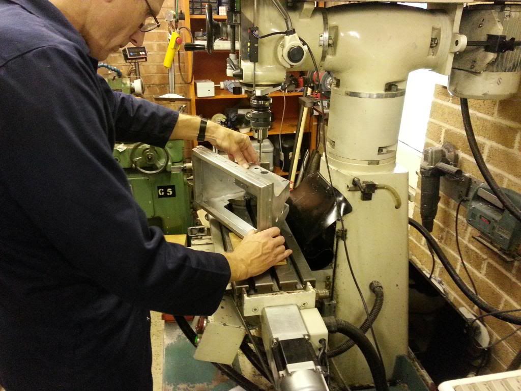
I then moved back to the 2-3-2, James had offered to ask Roger to
look at the ankles and leg rod fixings in the feet, so I took him up on the
offer, hoping to get this finished once and for all. The play in those areas was causing a lot of
wobble in the 2-3-2. So almost a full
day of stripping the legs on the Saturday, then I set off to Roger’s last
Sunday. We remade the JAG push-in
inserts for the ankles for a tight fit on the shoulder bolts, and made them a
little longer too. Then we redid the leg
rod fixings in the feet, these now cannot move, and the rod more easily rotates
on the brass bush and so it looked like it should solve the issues.
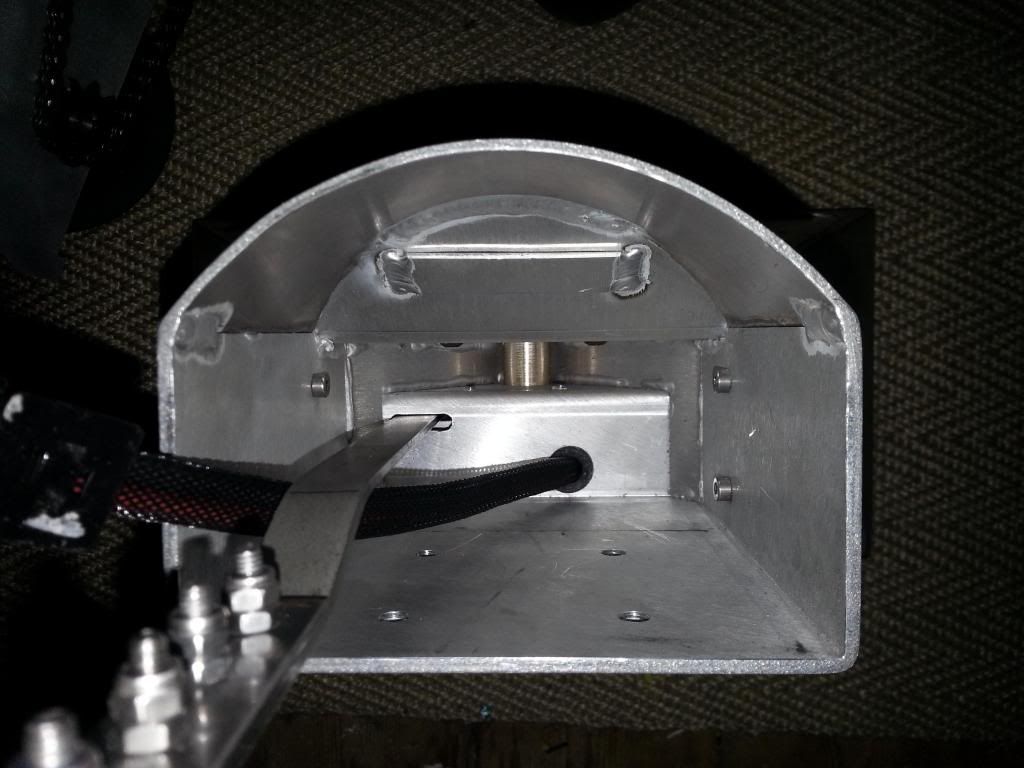
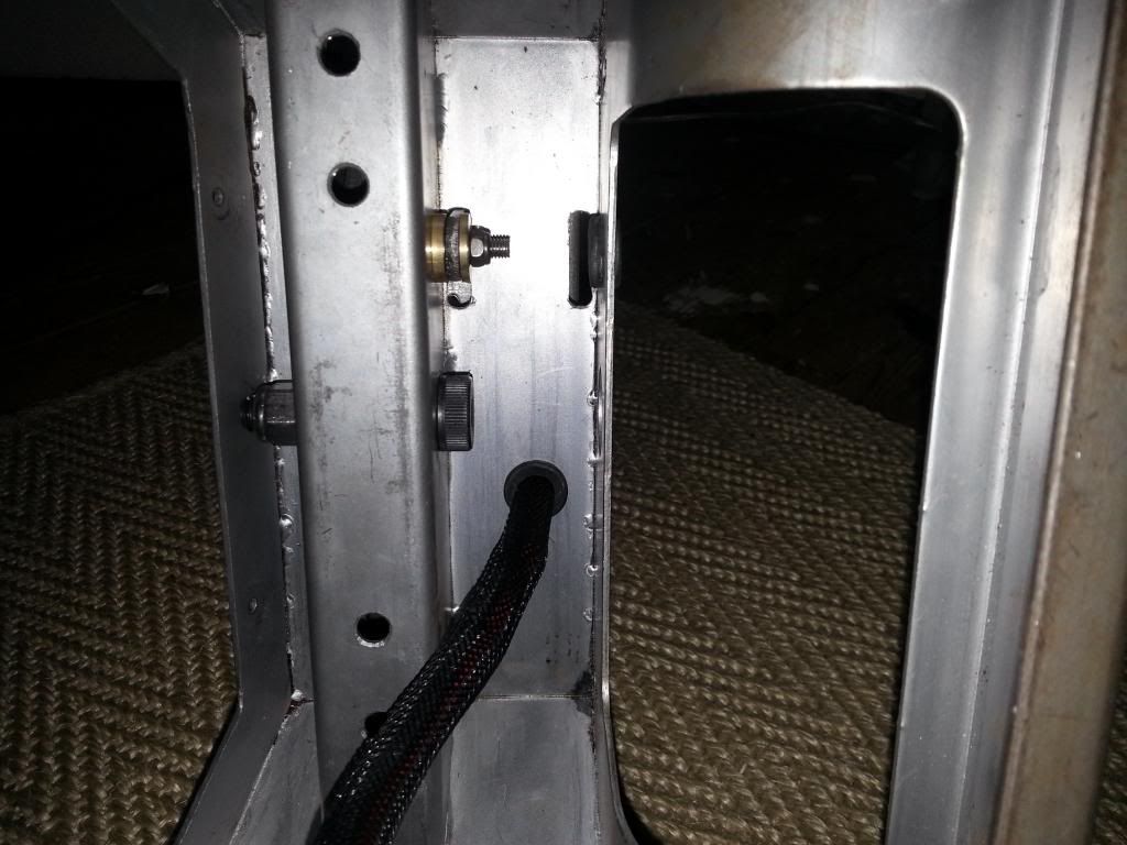
I also wanted to show you my ankle bracelet brackets. :)
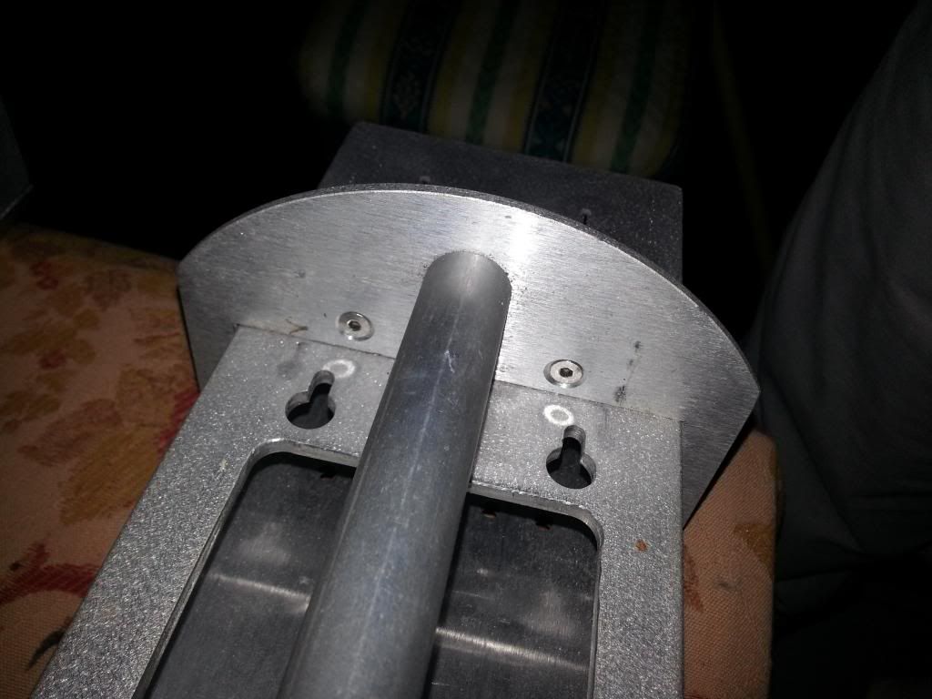
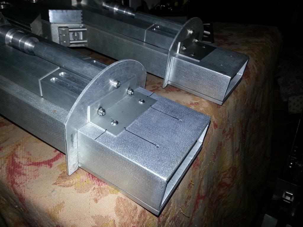
So then came 3 evenings of re-assembly! So much work to get it all back
together. James came over Thursday
evening to help as catcher. So tested it, it looked amazing, so much more
solid and reliable. But all the
positions were wrong. So I uploaded the
tweaked code…..then nothing. Dead. I spent about 5 hours debugging, thinking initially that I had knocked
out a wire and then that I had shorted the Xbee. Nope, I had accidentally deleted the line
Serial.begin(9600); not clever,
obviously the serial wont work without that! So once id found that I recalibrated all the
positions, re did the 2-3-2 code so that the signal to drive the feet stops
when the first actuator stops and not both (looks much better). It is so nice now. Really smooth and stable. There is one little detail of the bolts that attach the legs now taking
all the force so they undo themselves, but an easy fix with the right washers.
So here is my 2-3-2 as it should be, stable, balanced and
reliable. No face-plants, no wobbles,
just 2 legs to 3 legs and back. Maybe 60 cycles + now, and still running
perfectly. Long may it last. But if you are doing 2-3-2, it is a
nightmare, does require lots of work, it is different on a dressed droid, and
just because it does it once, doesn't mean it will do it all year long. Don’t give up, just keep finding more ways that don’t work till you find
one that does. My whole frame now needs a rebuild to allow more space for the CPU arm and claw, they fit, but not their mechs. :)
Anyone who says they have 2-3-2, unless you have done 100 cycles without issue, you haven't even started. :)
This Sunday we had another Builders day at my local hall. We had a really nice Dalek, a beautiful B9, 3
complete droids and 2 part droids, oh and a really nice mouse droid. There are a lot of talented folk in the UK.
The day included (or was taken over by) an Arduino workshop. I wanted to get a few people working with
arduinos and felt that the initial phase was the tough one, so doing an intro
and making something fun would be a good start and maybe help others to pick up
Arduino and run with it. It went really
well, they seemed to enjoy it, and were showing each other how to solve stuff
by the end, which is usually a good sign.
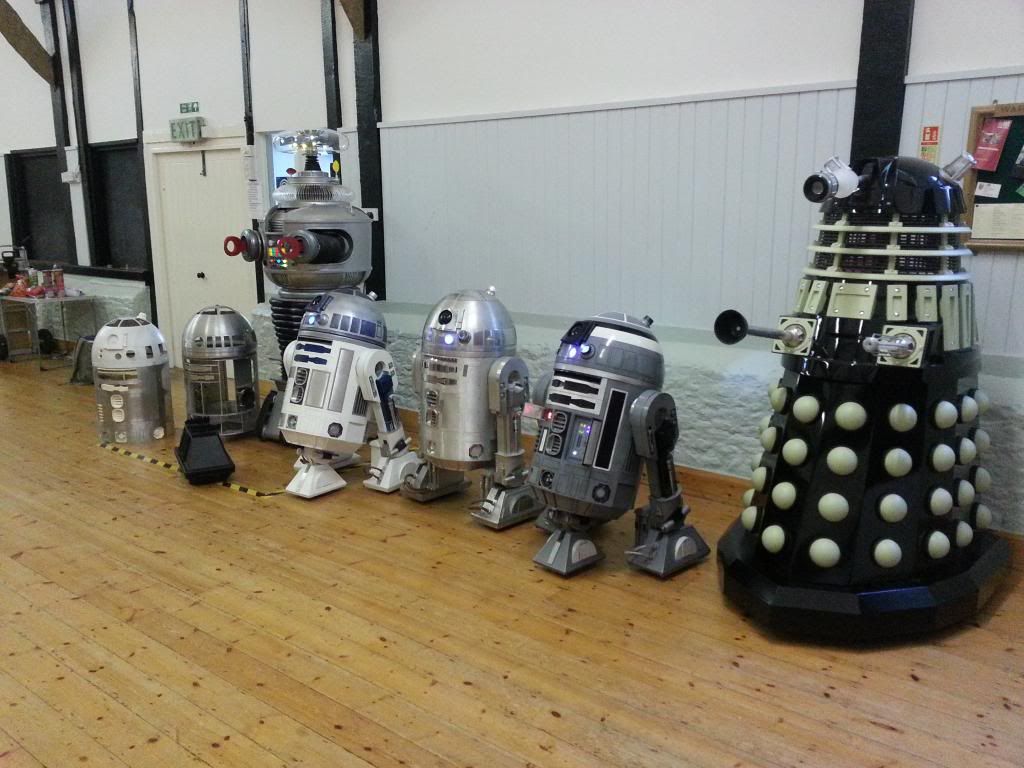
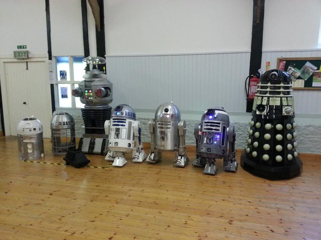
I had planned to do a load of testing in an open space, but didn’t
get chance. Next time.
I finally got the Relays for the feet, only a 5 week
delivery! Will be adding those ASAP.
Monday, 16 September 2013
Magic Panel Part 1
My Magic Panel arrived. It is a pretty thing. :)
So i soldered up the pins (or James did), and powered it up. Nothing, so read the guide. It defaults to flash every 8-12 mins. So i added the jumper to test the other options. It seemed like it had loads of potential, but some of the default scrolls and patterns seemed jumpy. So i started over. :D
The grid layout of LEDs is complex. The rows of 8 LEDs are actually the first 2 rows of the 1st chip and not in the same positions. e.g. Row 0 B11110000 and Row 1 B00001111 will turn on all the LEDs in the top row. So this was going to be fun.
I used a 2 dimensional boolean array (8x8) as what i wanted to see and mapped that to the actual LED layout. So i simply change the boolean array to say what should be on/off and then map and print that to the LEDs via the chips. It works beautifully. I can set rows and columns and work with it very easily now.
So once i got that setup i decided to do the pattern i had my heart set on. Random in and out so it is almost like a fade. I really like this one, it took a few goes to get it looking right, and being random it doesn't always look perfect, but im happy with it now.
Then i looked at shapes, i applied the Logo on the back of the PCB as one option, but when difused the image isnt easily seen, but it isnt horrible. :)
Here are a couple of videos of what it can currently do:
So i soldered up the pins (or James did), and powered it up. Nothing, so read the guide. It defaults to flash every 8-12 mins. So i added the jumper to test the other options. It seemed like it had loads of potential, but some of the default scrolls and patterns seemed jumpy. So i started over. :D
The grid layout of LEDs is complex. The rows of 8 LEDs are actually the first 2 rows of the 1st chip and not in the same positions. e.g. Row 0 B11110000 and Row 1 B00001111 will turn on all the LEDs in the top row. So this was going to be fun.
I used a 2 dimensional boolean array (8x8) as what i wanted to see and mapped that to the actual LED layout. So i simply change the boolean array to say what should be on/off and then map and print that to the LEDs via the chips. It works beautifully. I can set rows and columns and work with it very easily now.
So once i got that setup i decided to do the pattern i had my heart set on. Random in and out so it is almost like a fade. I really like this one, it took a few goes to get it looking right, and being random it doesn't always look perfect, but im happy with it now.
Then i looked at shapes, i applied the Logo on the back of the PCB as one option, but when difused the image isnt easily seen, but it isnt horrible. :)
Here are a couple of videos of what it can currently do:
So it is now ready for me to decide on when it should be used and add in the triggering, i have started working on the spreadsheet, and hope to have the I2C stuff added this week. Then i need to cut the hole in the dome and im good to go. :)
Tuesday, 3 September 2013
BHD Control BOM Mk1
BHD Control BOM
The following is a list of the parts used in my current electronics setup. This is subject to change and
still work in progress, but I have been asked a few times, and this will be a
useful base for a future write up.
Details on wiring to follow.
All Sketches, libraries, sound files etc can be found here:
Dome:
5v Dome battery with Auto Sense
(20Ah+)
e.g 20Ah Powerbank - £10.99 http://www.ebay.co.uk/itm/20000mAh-Universal-Power-Bank-Black-Backup-External-Portable-Battery-USB-Charger-/121165738787?pt=LH_DefaultDomain_3&hash=item1c360a7323
Slip Ring kit, boards
and slip ring – See Astromech.net for details
3A Switch for 5v
system
BHD Teeces Logics & PSIs
Controls the Logics and PSIs. This includes a Arduino Pro Micro or mini
etc. Plus Header pins, resistors for
voltage divider, leads crimps and covers etc.
This is setup as a 3 chain setup.
BHD Dome Servos and HPs
Controls 3 HP lights using PWM, 3 HP Servos for random and
controlled motion, and 9 door servos (4 pies and 5 lower).
Arduino Uno, Mega or
Nano : Recommend Genuine Uno
Uno:
Genuine: £20.80 http://www.hobbytronics.co.uk/arduino-uno-r3?keyword=arduino
Mega:
Genuine: £38.40 http://www.hobbytronics.co.uk/arduino-mega-2560?keyword=arduino
Compatible: £9.60 http://www.ebay.co.uk/itm/ATmega2560-16AU-Microcontroller-Board-USB-Cable-For-Arduino-mega-2560-Module-/350814658503?pt=LH_DefaultDomain_0&hash=item51ae2edfc7
Nano:
Genuine: £14.99 http://www.hobbytronics.co.uk/arduino-compatable-nano-v3?keyword=arduino%20nano&category_id=0
Compatible: £5.51 http://www.ebay.co.uk/itm/Mini-USB-Nano-V3-0-ATmega328-5V-Micro-controller-Board-Arduino-compatible-DR-/350850842192?pt=LH_DefaultDomain_3&hash=item51b056fe50
3 Bright White LEDs
3 220Ohm Resistors
Servos for dome
(4 for pie panels, 5 for lower doors)
I use Ripmax SD200 servos, so something suitable to lift the
panes, the specs are as follows:
Dimensions (mm): 25.0 x 29.5 x 13.9 Speed (sec): 0.14 Torque (Kg.cm): 2.50
James recommends these:
£10.00 (cheaper on ebay, but get what you pay for) http://www.hobbytronics.co.uk/hd1800a-micro-servo?keyword=micro%20servo&category_id=0
HP Servos – I
have a custom mech, and use Std size servos x 3. Any servos strong enough to move the HPs will
be fine. Currently the code only does
the Y axis, I hope to add code for the X axis too eventually.
Adafruit 16 Servo PWM
Controller (+Capacitor and pins), –
If servos are added
Relays for servo
power – If servos are added
5v 10A Dual Relay - £3.59
http://www.ebay.co.uk/itm/Arduino-compatible-2-Channel-5V-Relay-Module-Expansion-Board-/160981814618?pt=UK_BOI_Electrical_Components_Supplies_ET&hash=item257b438d5a
DC/DC converter for
servo Power – If servos are added
12/24v to 5v 10A converter - £11.89 http://www.ebay.co.uk/itm/DC-DC-Converter-12V-24V-Step-Down-to-5V-10A-50W-Waterproof-/200762957426?pt=UK_BOI_Electrical_Test_Measurement_Equipment_ET&hash=item2ebe679e72
Plus Header pins, resistors for voltage divider, leads
crimps and covers etc.
BHD DBC & Rear PSI
Rear PSI will also run on Teeces code if DBC is not added. This will allow control of 6 funtions from
the dome bumps e.g. random sounds on/off, hi/low volume etc.
Dome bump controller
– See Astromech.net for details of the part run
Work in Progress
Also need a few header pins etc.
BHD Magic Panel
Magic Panel – See
Astromech.net for details of the part run
This may well become the controlling Arduino for the Dome
servos and HP, but needs coding and testing.
Work in Progress
Body and Feet
12v main Battery – LifePo4
Tracer? SLA – Up to you. Power depends
on weight of droid and run time needed.
This only runs the ESCs and the 3 motors, the DC/DC converters, the
amplifier and the 2-3-2 system. The rest
runs on the dome or body 5v supplies.
All 12v supplies are fused, and relays are added on the feet drives and
on the servo power feeds to prevent rogue start up issues, and improve overall
safety.
5v Dome battery with Auto Sense
(20Ah+) (see above in dome section)
This powers the Master, relays, MP3 Uno and Shield, the Body Uno, 2-3-2
Uno, Adafruit and all the LEDs
Feet Motors – Up
to you, recommend NPCs for alu droid
Dome Motor – Up
to you, recommend Pitman
Fuse Holder for 12v
Supplies – Recommend RigRunner 4008H + Suitable fuses for each 12v circuit.
3A Switch for 5v
system
BHD Master
Master runs the speed controllers, dome positioner etc and
communicates with the pad.
Uno (see above)
Xbee
XBee Pro 60mW PCB Antenna - £39.60 http://www.hobbytronics.co.uk/xbee-pro-60mw-chip?keyword=xbee
SparkFun XBee Shield
Sabretooth 2x25 –
2 x 25A ESC For Feet Drives if lower powered motors you may get away with less
current.
Syren 10 – 10A
ESC For Dome Drive
Dome pos Pot
(Optional)
SparkFun 10k Rotary Soft Pot £14.56 + P+P http://proto-pic.co.uk/softpot-rotary-potentiometer/?gclid=CK6pvojgrbkCFZShtAodDlgACQ
Feet Relays
2 x 5v 30A Relays - £8.40 total http://www.ebay.co.uk/itm/1-Channel-5V-Relay-Module-30A-High-Power-F-Arduino-AVR-PIC-DSP-ARM-SLA-5VDC-SL-A-/300669043376?pt=LH_DefaultDomain_0&hash=item46014582b0
Also need a few header pins etc.
BHD MP3
MP3 Shield and controller
Uno (see above)
SparkFun MP3 Shield
Ground Loop Isolator
Stinger Ground Loop Isolator - £15.28 - http://www.ebay.co.uk/itm/Stinger-SGN20-Ground-Loop-Isolator-/321111249429?pt=UK_Sound_Vision_Other&hash=item4ac3b8d215
Amplifier
Any 12v amp, 2 channel, just needs RCA on inputs from GLI
connectors (above) and speaker outs, volume control is useful, but not
essential. Recommend a min of approx. 2
x 20W RMS power.
Speakers, cables etc
Suitable speakers for amp, and wires including headphone to
RCA adaptor for the Shield to GLI
Also need a few header pins etc.
BHD Body Controller
This will run all Body Servos, CBI, Data Panel and Vegas
Kit.
Uno (see above)
CBI Panel – See Astromech.net
for details of the part run
Data Panel (Optional)
– See Astromech.net for details of the part run. I am
not using this on mine so control is
basic, but the random mode looks great.
Vegas Kit – RGB
LEDs in LDP and Coin Slots
25 LED Pixels - £11.64 http://www.ebay.co.uk/itm/25pcs-12mm-IP65-Waterproof-Full-Color-RGB-LED-Pixel-Modules-with-WS2801-2801-IC-/281154817503?pt=US_Car_Lighting&hash=item4176220ddf
Servos for Utility Arms
and Doors (If so add 2nd Adafruit, 2nd DC/DC, Dual 5v 10A
relay and more Servos - see above)
Plus Header pins, resistors for voltage divider, leads crimps
and covers etc.
CPU Arm and Claw to follow.
BHD 2-3-2
Optional – But complete and working, please ask for details
if needed. Also feeds back status to
master to say if in 2 leg mode.
Pad
BHD Pad
V1 – Changes to follow
Arduino Mega (see
above)
Xbee (see above)
SparkFun XBee Shield
(see above)
Screen 1604 LCD I2C
PS2 Pad
NOTE: Must
be New and Genuine. Do not attempt to
save £10 on this part, you will regret it.
Box
Battery
Up/Down USB Cables
Header pins, connectors, leads, resistors etc
General list
Solid core wires, lots of colours. :) For making up shields
Header pins, lots of them, all sorts
10k resistors for pull-ups where needed
Crimps and PCB connector covers in various sizes (details to
eventually follow)
Crimpers for above are useful, but not essential
Wires for power and signals, often servo type leads, but
also for feet motors (check your stall current values)
Solder
Multi-metre (Essential)
Subscribe to:
Posts (Atom)