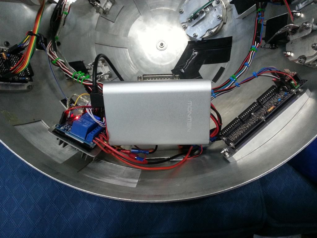
I posted this elsewhere too, so please forgive the copy/paste. :D The refurbishment/upgrades spell is done for the moment. It has been fun, lots learnt, lots of tinkering and touches I’m pleased with. Took a while to come good, but really feeling like a complete droid now. I have finally done/added/tested and tweaked the following. 1. Magic Panel, used on lots of calls. 2. Dome Bump Controller – Running rear PSI. This is not currently connected for commands from buttons, but is on I2C for PSI control. 3. Replaced dome servo Mega Arduino, with a Nano and shield 4. New Teeces code that varies the effect 5. Relays for Utility arms, Door Servos, Feet and Dome drive 6. Current and Voltage metres for Body and Dome 5v batteries 7. USB breakout port for Body Arduino programming and rewiring 8. USB charge port connected up and able to charge PS3 pads 9. Dome power switch 10. Connected the 5 body door servos and redid Utility arm setup. 11. Moved volume knob to the front Octo Port 12. Reconditioned and checked over the 2-3-2 system (still not 100% happy, but working OK) 13. Replaced the missing Battery Boxes, Hoses strips and KHFs 14. Removed and replaced all dome doors 15. Fixed all loose door trims and a general service Just need the Battery Harnesses and he is pretty much done externally and doors etc. Still got the gadgets to go. Here is a video of my progress, showing the new bits and them working with the combo scripts. I do love that magic panel, such a cool little thing, shame it’s not that clear in the vid.
I cant believe I hadn't spotted it before now, but the HPs were connected to the wrong points, so they weren't flashing and moving at the same time. An easy fix. :D Battery (or one of the options) arrived today, so popped that in place. So much better. The battery turns on with current draw. Meaning the switch is now in control. :D No more fishing for the battery button.
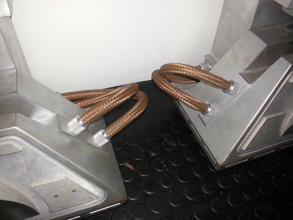
Long term, if I can improve the slip ring connection and position/configuration then the dome will be great to use and remove when needed. Only downside will be the need for a new slip-ring on each new dome. Next up were the hoses. I had to strip the feet to do this job as the drive train gets in the way. Same way as before, 10mm rawl plugs inserted into the back of the KHF to retain the hose. But the cave makes these jobs so much easier. Less than 2 hours for both sets. :D Still need battery harnesses, must keep an eye open for the next run.
So that is him done. Ready for final assembly tomorrow night, and the last bit of testing. Then i can relax and tinker with the code and drive him all weekend long. :D Feeling much better about him today, I glued up a few of the lose door trims and tweaked a few servo spots and revisited the way the dome sits, it all feels much better now.
Expect an update vid of the whole thing over the weekend. I forgot about the DBC control! The PSI triggers fine, and the buttons do the colours, but the signal lines aren't connected. Too late to test that now, enough is enough. Will wait on that one. :D
I got the skins back on after the strip and was pleased to find the Servo positions were still fine. :) So one less job to do. :D
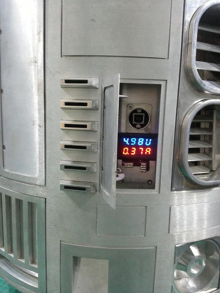
The Meter looks great and the USB programming port still works fine.
So all back together, busy tweaking timings and uploading code while testing, and I spotted a few key things.
1. The dome gear change has caused all sorts of issues with the dome pot code.
2. The relay for the dome didn't have any effect. Not good.
3. The relays for the feet draw approx 0.3A for the pair, and only about 0.06A for the dome relay. I am glad I went to so much effort on the 2-3-2 relays to get them off in 3 leg mode. :D
4. I seem to be having a few random 12v battery connection issues, the T-Bar wont connect perfectly every time. I will send this back with the battery when it gets serviced. Once properly connected it seems fine.
Starting with the dome pot. It now needs more speed to turn at all, so it isn't as accurate due to having to decrease the sensitivity and adjust the speeds and distances at which it changes speed. I will see if it runs in, but currently I think it very likely I will go back to the A&A plastic gear eventually. But I tweaked the code to compensate and it seems OK, but not quite as spot on as before.
Then the dome drive relay. :( Note to self: If you tie the GND of all sorts, don't try and add a switch on a GND line! Syren 10 was in an nasty spot under the 2-3-2, so I tried to cheat and cut the GND with a relay. That doesn't work due to the signal GND. Muppet. Don't cheat, do it right. So I rewired the dome drive and the relay, it is a horrible fix, I will most likely look at this again when I redo the 2-3-2 wiring and code. I simply ran an extension of one motor leads to the relay and then back to the syren, ugly, but it works.
Then I added the timeout in the code for the feet relays, when on, 60s after any dome or drive stick move, or any script call sent, they now turn off. :D That should add a few hours runtime on the 5v. :D
All tested and working fine, I wont say I'm 100% happy yet, it could do with more fiddling, but 'good enough for this job' as they say.
While I was thinking of code, I realized I had uploaded a Teeces version I had only bench tested. :D It varies the speed and number of LEDs so it looks more like a true processor or memory state, I love it, just makes it that little bit more organic. Also the PSIs only sweep, but from either direction. Just a little cleaner. Here is a vid. I hate trying to film LEDs, this is the best I could do, sweep is much better in person, but you will get the idea. :D
With regard to physical electronics, it is just the feet left to test. :D And id love to add those new scripts and sounds. 9 days to go, 2 being weekend days. Must get at least 2 evenings driving in before letting him lose too. It can be done, but I'm starting to run out of momentum now. I'm sure I will still end up working on him till late the night before! But feet next, after one last reassembly and test of the body.
Well it seems fitting that the rebuild is still going strong as we pass the 10,000 mark on the blog. Carrying on from the door servos, next I looked at the dome drive pot setup, to make sure the position control was working on all calls. I found an issue with the dome drive positioning script calls, not dome random, but just the user based calls. I had disabled them! So sorted that in the code and got all the dome pot stuff working well adjusting timings etc. I've noticed the delay in transmission since moving back from my PS3 test code. I had a similar thing on the PS3 stuff, so I know it can be addressed. I will have to redo the Master base for that upgrade, so I will fix that then. This is still fine to control him, but I'm now sure it can be improved for more response, even with the accelerations. Then I redid the body door relay wiring and sorted the code to stop the boot twitch. Works beautifully, I also adjusted the timings of the relays, it is only on for a fraction longer than the servo needs and so the droid hardly buzzes even tho the servos are a little too closed to pull the doors up. It has highlighted the need to add a 'close all doors' call, because when opened by hand when not powered, you currently cant close the doors, because the droid thinks they are closed already. :( So that was the body done, retested and working well. Dome time. Popped it on, Powered it all up, only the Magic Panel worked on I2C.....odd. DBC had the I2C wires on the wrong way, 1 sorted. Teeces looked fine. so left that and looked at the Servo Unit, after a bit of research I found I had used the wrong Nano pins for I2C. After a rewire of the shield to add the right long pins, the servos and the Teeces triggered fine. So looking back at it all and admiring, I spotted the front HP was dead. :( After some debugging it was a bad lead, so I added new terminals and that was it. All the physical elements, apart form the feet and legs done. Sort of. Dome is now fully tested via I2C, all new and old elements working well, body fully tested with all the servos, vegas kit and dome pot triggering sorted, 2-3-2 tested and serviced. Magic panel and DBC trigger perfectly via I2C. I then tweaked all the scripts, got the timings sorted and generally played with the current combo calls adding the new elements. Edited a couple of dome servo spots and decided that was enough of the old. The new dance scripts were next. This is a WIP vid of some of the early combo timings:
Body Ammeter and Voltage Display: But again I got side tracked. The more items I add to these 5v Lipo batteries, the more I am amazed at what they can run. So I was interested to see how much 5v current the setup is using. I got online and found some Voltage/Current meters, nice little LED ones, only £4 each. :D They arrived on Thursday, and i couldn't resist playing.
http://www.ebay.co.uk/itm/390799784629?_trksid=p2060778.m2749.l2649&var=660222083208&ssPageName=STRK%3AMEBIDX%3AIT First I rigged up a little breakout board, this takes a USB in and out, and powers and feeds the meters. D Eventually after some fiddling and a few broken leads, I had the device reading voltage and current, and tested it on the R-Series rear logic, using the brightness pot on the back I could go from nearly 0.9A to 0.1A, but it seemed about right on 0.3A to me. But concept proven. :) So i then stripped R2 again, removed my rewired panel and started pondering. :D By rotating the bus/bridge there was enough room, but where was best? Looking at the holes i already had and the current locations, i decided simple was best and added it to the centre of the panel and added the bus below.
I wanted to make a diagram for the doc while it was fresh in my mind. Below is the layout of my USB power and programming setup with the display meters, well this is what I would have done, mine differs slightly:
I tested the body battery draw before installing the meter, the body runs at less than 0.4A most of the time with peaks at approx 0.8A when going bonkers. :D The dome seems similar, 0.25-0.35A with peaks of about 0.9A. Voltage runs a little lower than id thought, but all seems to be running well, so who cares. :D The PS3 pad draws 0.33A with a 0.5A jump on connection, phone draws less than 0.2A, so I think I could possibly get away with feeding the dome supply through the slip ring and removing the dome battery. But not yet, this works, and halves the draw on the batteries, and lets the dome run stand alone. Dome Gear: Dome gear arrived, James made a start on it for me, thanks dude. It is very thin, only 1/8", but nicely cut, with a little tidy it looks the business. The way I mount my gear and rockler is different, I mount the gear to the bottom, not to the top, as a result it needs approx 2mm off the radius to fit. Took a few hours, but trimmed back fitted it and got the rockler spinning well. The A&A gear was really smooth and a great profile, it was very tolerant to positioning. With the new gear, both the A&A head and the Ali head's teeth were hitting the main ring teeth not catching them. The original motor location was too far out for this cog, so I remounted it about 4mm closer to the gear and tried again, position is great, less than 1mm offset so there is almost no slop, but still the Ali ran really rough, and the A&A was a little sticky. :( I want the ali one to work, it looks better, so I persisted. I ended up shortening and reshaping the A&A gear head piece, it now runs pretty well. I'm going to run it in and see how I feel, it may smooth down with use, I haven't powered it up as yet, or refitted the front skins, so fingers crossed.
Body Ammeter and Voltage Display: So while I'm getting side tracked I may as well have a quick look at the dome meters. :D Same plan as the body, but just power at this stage, not the serial lines. I made up a 2nd Display breakout, and had a bit of a ponder. I wanted to be able to see it if working in the dome, but also wanted to be able to see it when he was running. I decided to mount it at an angle in the silver door to achieve that. I cut and bent a strip of 1mm ali, shaped the feet, and stuck it to the dome. Then I thought about how I hate fishing in the dome to turn it off, so I wanted to add the switch again, it was useful. If I did that and got a power sensing battery (my last ones are pants and not their stated capacity), I could then turn the dome on and off externally. :D
So with that decided, I had a think about the dome battery location, currently it sits on the base plate, but that is a pain because all the electronics are on the dome itself. The rejig in the dome had unknowingly revealed the perfect spot. I will order a new battery that will turn on with draw, for now this works, but is on via the button on the pack.
So just need to reassemble the body, finish the feet, do those new combo scripts and I'm pretty much done on the current refurb. 2-3-2, Master and Pad will be the next big set, but that can wait for now. :D I will post a vid of the revamped R2 when he is rolling and the new scripts are done. I would love to remount the slip ring the other way up and swap the pot to the dome and wiper to the body, but that seems like a lot to go wrong with less than 2 weeks to FACTs.
This is wearing thin at times, everything is a hurdle! Getting there, but slowly.
The servos put up a fight. First off the servos wouldn't power up. I checked all the wiring, tried the relays both ways, checked the step down converter all sorts, fixed a few things that weren't broken, then found a lose connection. :D
So servos working, now time to find the positions. Powered up, found the top utility arm spots, left it open to be able to open the other the same amount and while mucking about with the bottom one about 7-8mins later the top one gave a twitch and gave up. :( Fighting that spring for too long isnt good by the look of it.
Bottoms! I was just about to give up for the night when i had a thought, dug through my stash and found a spare servo, a perfect match for the broken one. That never happens. :D So it was broken for all of 10 mins. :D
Tested the uploading and powering from front and back and all works seamlessly. Popped the body code back in, booted up and spotted a silly mistake. I had wired the relays the opposite way, and allowed for it in the code, so the relays dont stop the boot twitch as they do on the dome. That is tomorrow's job!
But 5 body doors and the redone Utility arms, now all on relays so they can be opened by hand. This has been a job i have had on the cards for maybe a couple of years, the servos have been in the body and moving for over a year! So nice to have it done.
Edit: Not worth a proper update, but scripts edited, dome position call issue fixed. New scripts to follow. :D
I powered up the dome and found I'd made a rookie error on the Nano shield, sorted that and finished off the code for the magic panel and DBC. Powered it up and had a play with the rear PSI colour via the buttons, and setting off DBC combo triggers. But the magic panel just sat there, powered and working, but no sign of anything special. :( I had to sort that, so I added quite a subtle a little random flash spell in every 20-40s (after last button press, and timing in the video is different). It's looking good, assuming the I2C triggering isn't an issue the dome is looking great.
So with the dome now working well off droid, I would need the body working for the next stage of testing.
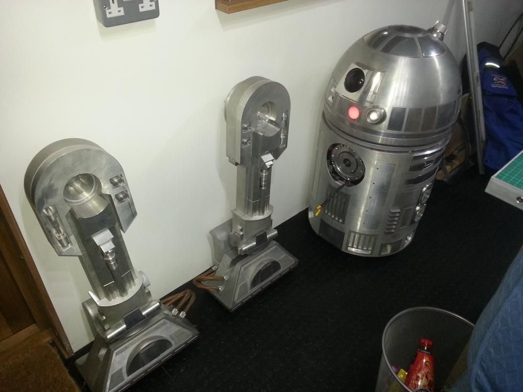
I had James over last night, he kindly attacked my droid with a scotch bright pad between jobs, it's looking better than ever. :) Pic at the end. :D Spoilers. ;)
I decided that we would do the servo positions first. So new remounted the new 5v body battery, powered the body up, and the battery cut out. There was a short. :(
After a lot of mucking about and debugging I found the issue; rather embarrassingly it was the shield on the body unit, it had been mounted wrong. So now working and making noises, I finally had chance to test the volume knob, IT WORKS!!! So pleased with that little change. :D
So the body was now powering up, but my thoughts turned to how I would upload the code and not have to strip the droid to change cables the next time I need to move the body servo spots After a lot of head scratching and chatting with James, we had come up with a very cunning plan, bit by bit. The USB lead is just 4 wires, so if they were broken out somewhere, then they could possibly be connected to the PC instead. So I made a lead, snipped a USB lead, and added 2 4 way connectors, one male one female and connected an Arduino to the PC and it worked as normal. :D
So with the ability to jack into a lead, what I needed was an easy way to sort all the coding issues, and power all the units from one source, but swap between Arduino serial ports for coding.
The lead from the battery is USB, so that would be one PC connection method, but I wasn't using the Charging ports in the door below the CBI and they were never going to get used. This seemed like too good a chance to miss. I converted the top Charge port to a Power and serial USB port, fed that to a manual bridge to allow me to swap between that feed and the 5v battery and so I had choice of supplies. I had a nice Up/Down USB connector, to do so I flipped the port 180, so officially the USB input is the wrong way up, but it was a nice short wire.
Then I needed to be able to select the Arduino for the serial. I added a run of double header ports, the first 3 connected as TX and RX rails. This was fed from the bridge. Then I added sets of 4 pins for the units. I then tied the 5v and GND rails to distribute the 5v power. I only added 5v + GND for the Master, as the xBee has to come off, but i might look into that if this works as well as i hope it will, So using a jumper piece I can now select between 3 Arduino from 2 locations. The serial works well on all from all. :D
I then saw the CBI charge output, I hadn't been hooking this up recently, but it would be useful, and thinking about the upgrades, would be great if it charged the PS3 pads as well as any dumb 5v device. So I added 2 more header pins to the bus power rails to power the charge port. The PCB of the Duracell PS3 charger has little connectors, I removed one and added some pins and ran that to the charge port via USB. Im pretty sure the PCB will limit the current to .5A per port, so that should help with possible over drain issues connecting hungry devices.
So here it is, from the bottom up is the Selector+Bus/Bridge board, Then USB in port, then PS3 pad charge PCB. Then USB Output port and CBI PCB.
The Bridge is the upper spot for the Port, and the lower for the Battery. And the Selector is Bottom for Body, Middle for 2-3-2, and Top for MP3. I will add something to cover the exposed points.
So this is the rewired PS3 pad charging CBI port and USB breakout Input/Output panel. :D
And here is the cleaned up naked body. Cheers James. :D
So major progress. No more fishing in the droid to upload code, Hope this makes life a lot easier. The servo spots are next. :D But I now know the droid powers up and talks to the PC, and the dome seems fine, so I'm hoping for a smooth run to the finish. We can dream.
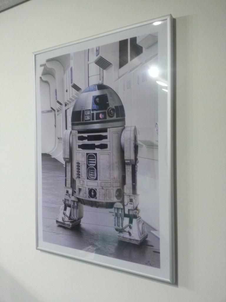
Christmas came early today. Wiz AKA Paul Johnson AKA PaulJWIZ, call him what you will, this boy has some serious talent. Has just sent me a copy of his new print. It is fab, really stunning. I'm so in love I'm almost tempted to paint R2-BHD. Thanks dude, love it.