Sunday, 30 November 2014

Front Skin work (Body Unit)

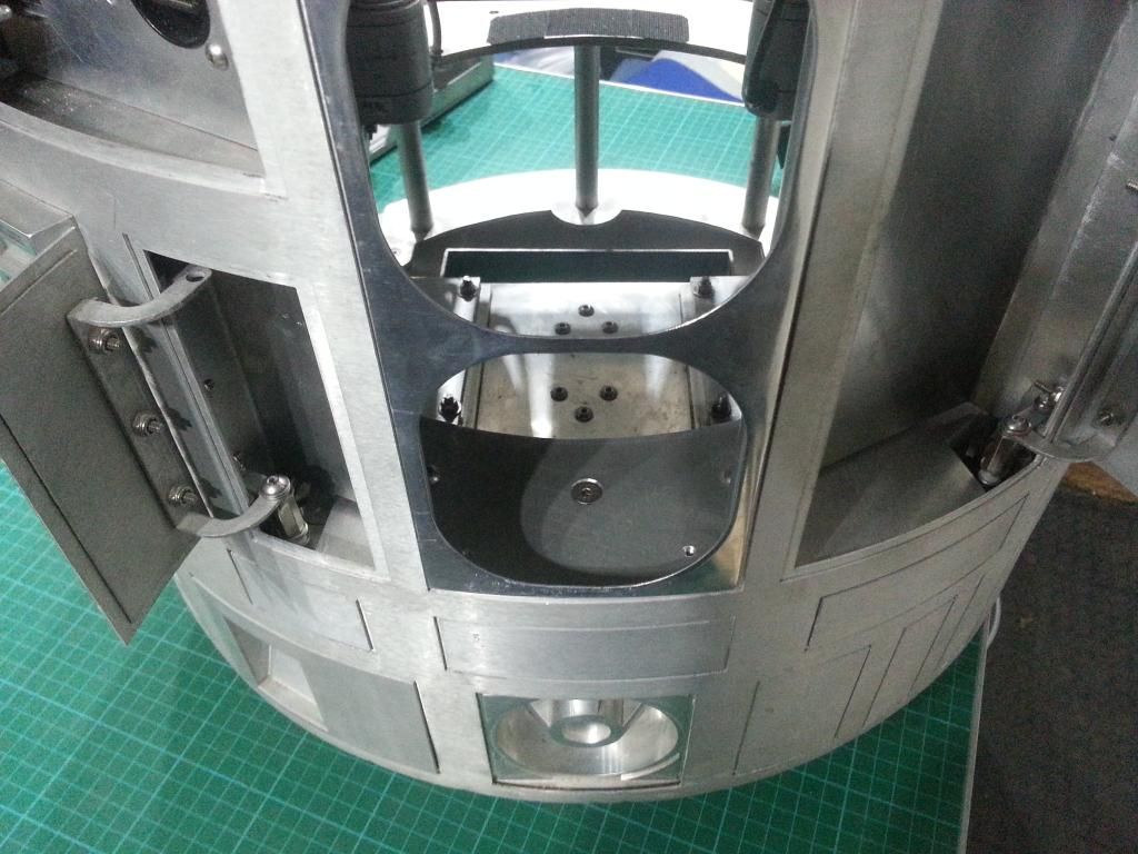
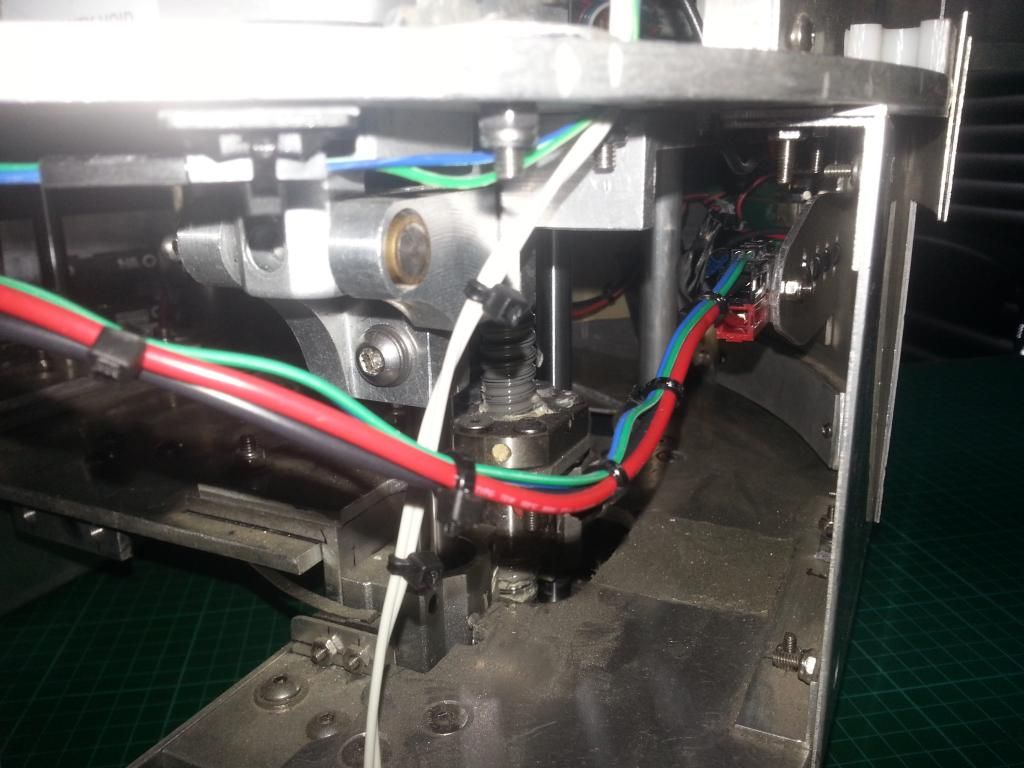
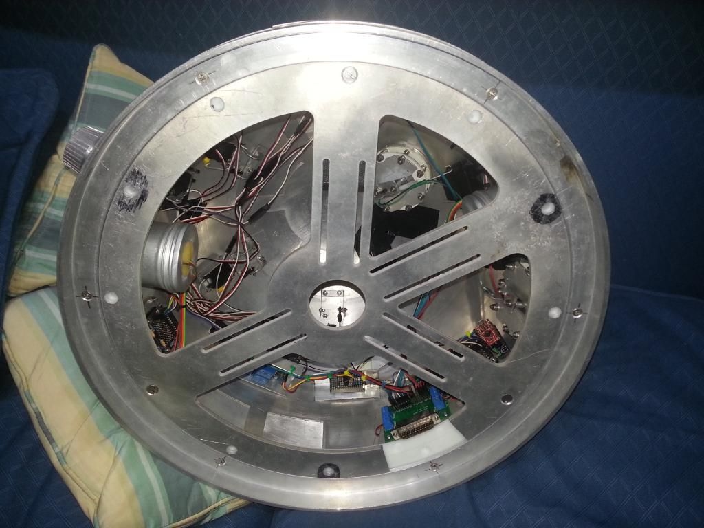
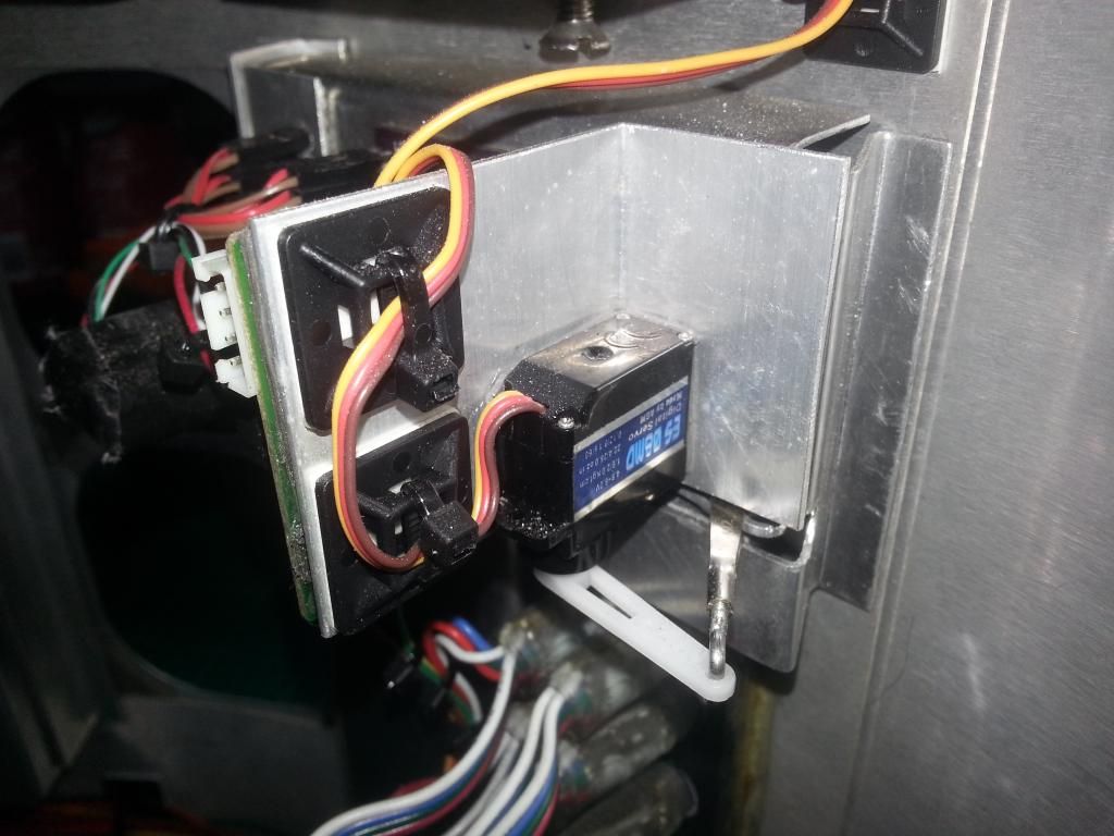
I spent last weekend rewiring the body.  4 of the door servos attached to the skins no problems, but the CBI didn't have the space around it, so i was forced to mount that one to the back of the CBI pan.


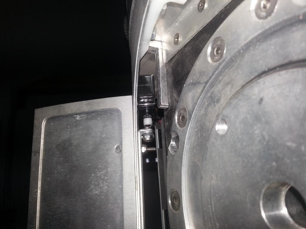
When the base was done, i offered up the skins to the frame and found that i would need to cut a lot of the frame to fit it.  So after a bit of a ponder i decided to move the long door servos to the top of the hinges so that the frame wouldn't need as much adjustment.

If i were starting fresh, i think that with the right arm carrier one could fit all 5 servos to the skins, with the long doors and the big door and CBI servos above the doors, and only the small door below, then the frame would only need one cut out and would be a really neat setup.

So with the body rewired again i marked and cut the frame to accommodate the other servos, and the front skins were again able to be fitted.  I also cut access to the master Arduino port. :)


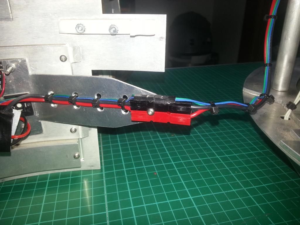
That left the wiring connections.  So after a lot of thought, i added an arm to the back of the pocket vent, then glued a 2 pin servo type lead to the top of an Anderson connector and hey presto, one connection for all 4 wires. :D That is accessed via the back when the front skins are fitted, or can be pulled out for off droid testing, i even made up an extension to allow it to be used more easily when the legs are on. 


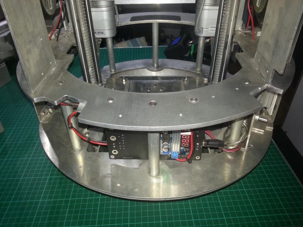
So all was looking good, by Sunday morning i was ready to test.  This new setup allows the body to be tested off droid, so servo testing was easy.  But the 8A UBEC cant cope with the Utility arm servos, especially when run with the springs.

While testing the servos i tried the servos on 6v, and they are SO much nicer, more solid, quieter and faster.  So i looked about and found myself a 15A variable buck stepdown, i will run the body servos at 6v.  I have disabled the arms for now, and have finished the rest, but will redo the servo supply when it arrives.  

But mid Sunday i wasn't feeling well so decided to stop for a bit.  3 days later i was still in bed and couldn't face R2, so i decided to wait for the weekend.  

When the weekend arrived, i recoded the body code to added the changes to the layout and add servo positions, and started testing.  A couple of wiring issues later i had the door servos, CBI, Vegas kit and charge port working well.
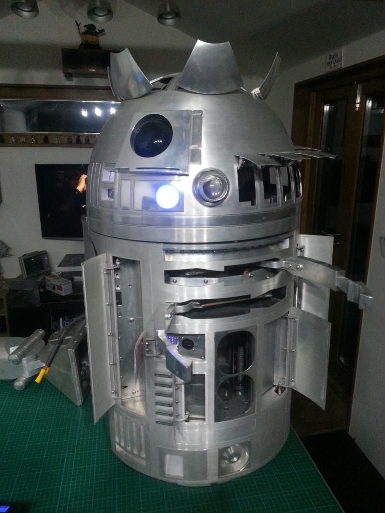
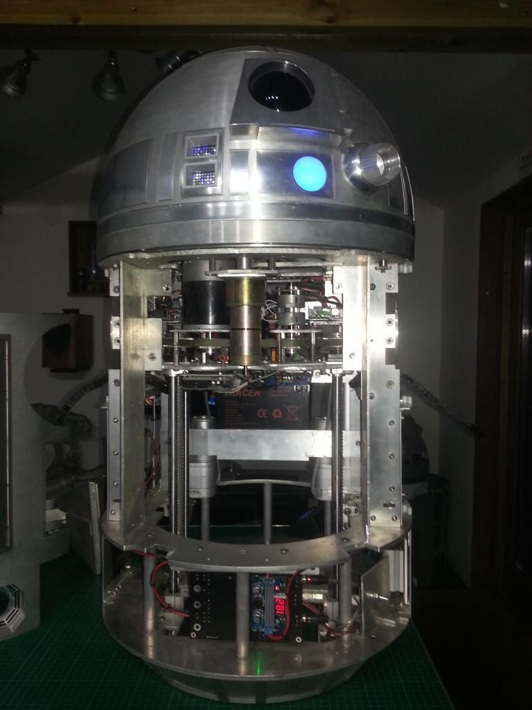
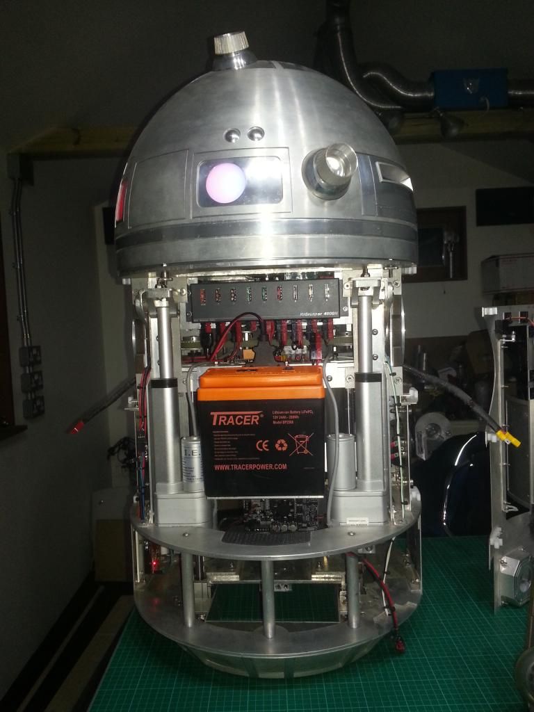
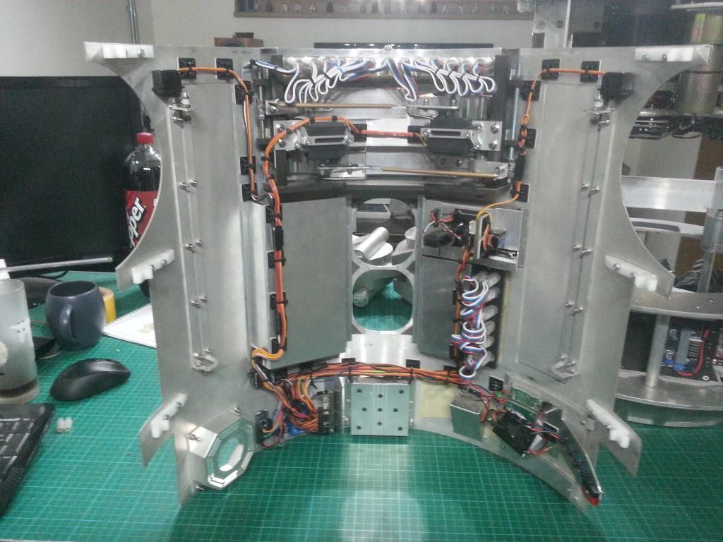
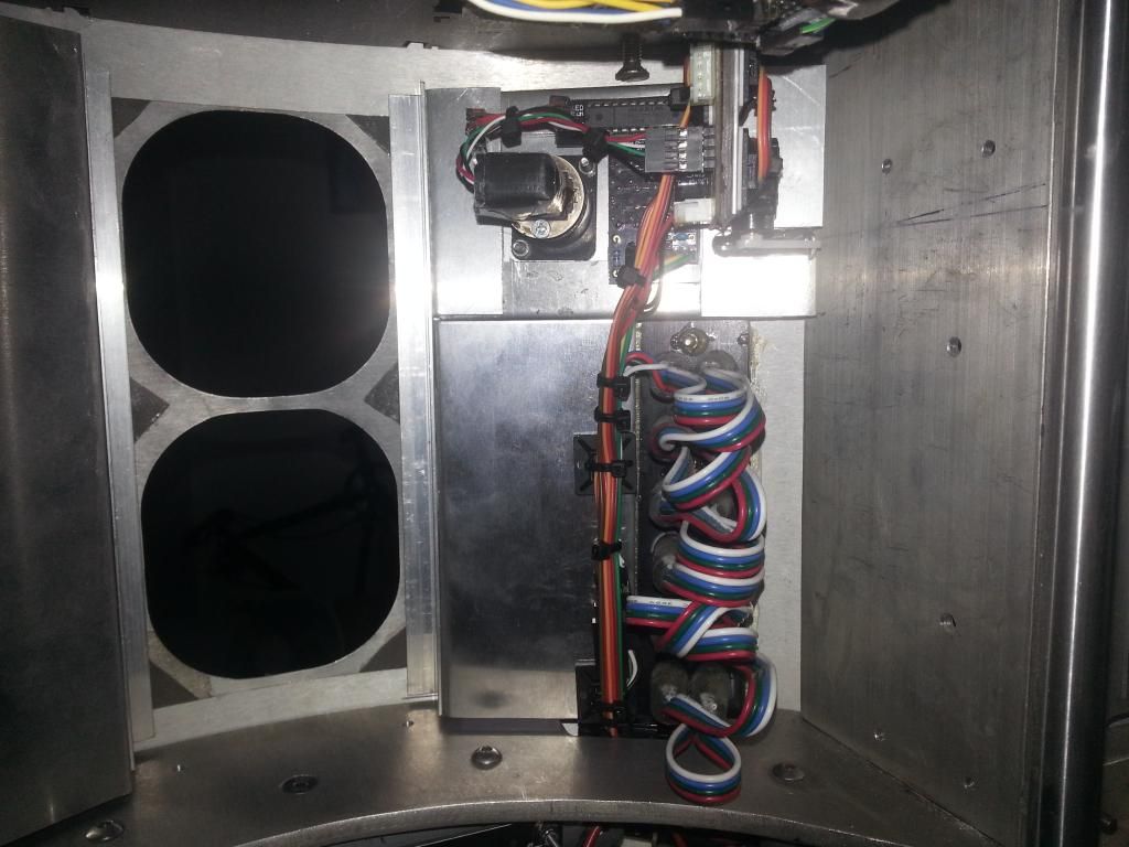
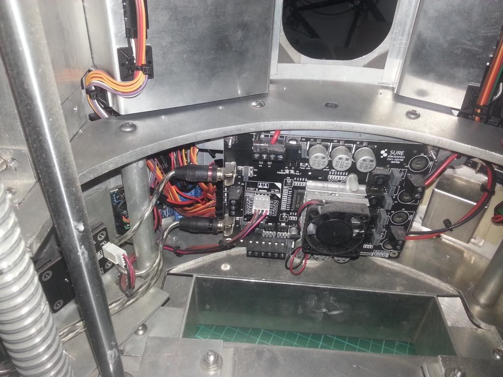
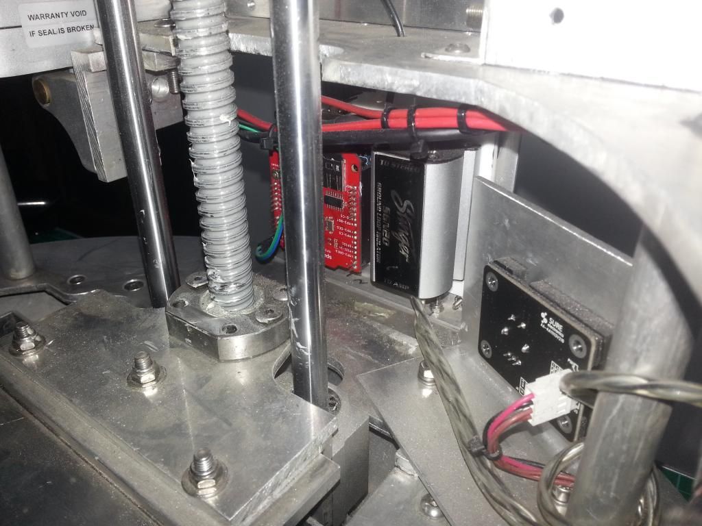
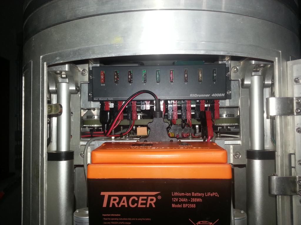

The body unit still needs a little TLC, but i ran out of cable ties, and i need that stepdown, so i will finish that off when i can complete it.

The frame looks so empty!  Really pleased with progress.  The droid is now much easier to run, with the dome and body being standalone testable units.  Id like to make the master unit removable, and improve MP3 and 2-3-2 disconnects from that, but that can wait for now.

While doing all this, it has made me think about the Vegas kit, it is a great effect, but the cheap kits arent great, the wiring and voulme used is rubbish.  So ive been looking about, i can fit 33 Neopixels in the LDP and redo the  Coinslots too, all to be low profile and neat and tidy.  Just the cost and removing the glue from my current setup. :(  Will save that for next year, and when i do droid 2 i will redo both kits.

But it has left me thinking.  All 3 legs could be better and easier to remove.  I am going to do a similar thing to Flipside and add a quick release to the Centre leg, that can be a Christmas job.  But im having trouble thinking of a suitable method for the outer leg release, they need to be so solid. :(  But i do have a plan to do away with the need to strip as much of the leg and allow the wires to connect automatically, so maybe better but not perfect.

I now have room for all the dome and body gadgets, and space for my docking screen.  It is a great step forward and will make future mods a lot easier.

Saturday, 8 November 2014

More Rewiring Progress

More steady progress.  The droid, all apart from 2-3-2 was totally stripped of all electronics.  With the aim to look at it all a fresh and try to make it easier to use, less likely to shake stuff loose and to use spaces that are currently wasted, freeing up space for more future goodness.

I have wired up a panel that will mount to and behind the Rigrunner.  This attaches to the top ring of the frame and holds:
Rigrunner
Master Arduino with Xbee shield
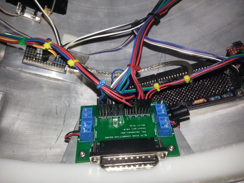
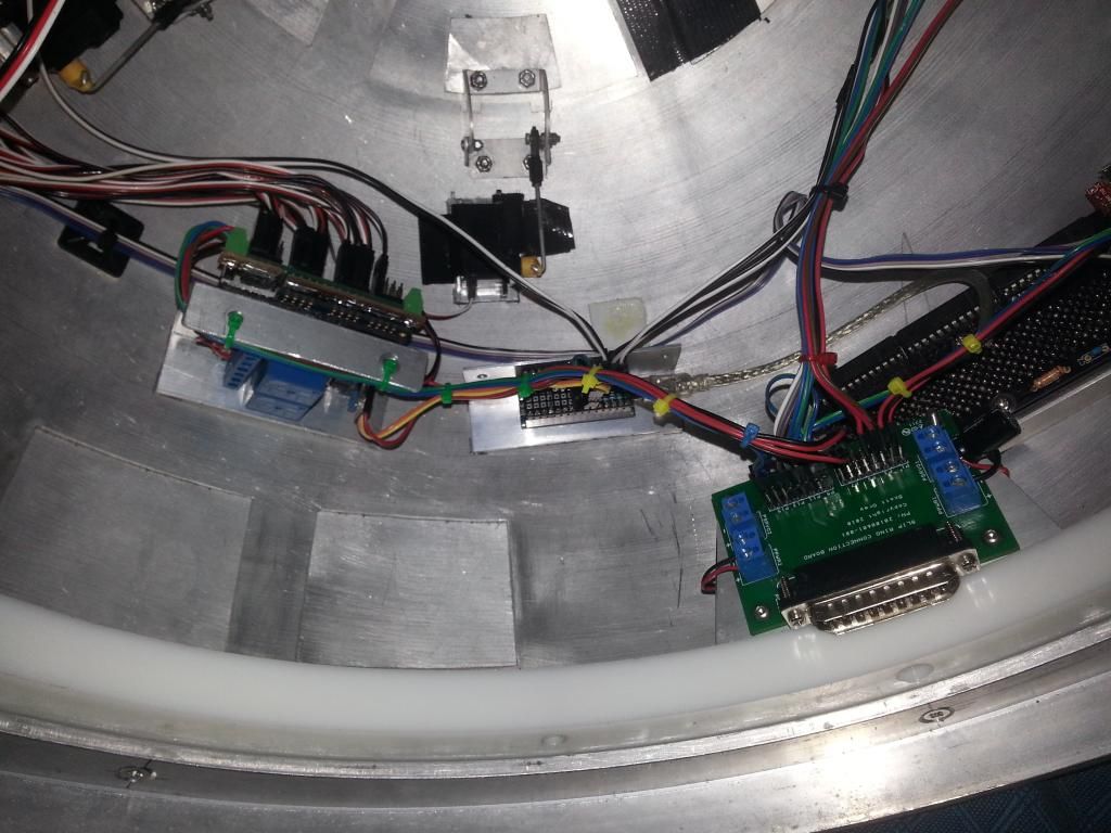
Slip ring and connector board (Acting as I2C and 5v Bus for Master, 232 and MP3 Arduino)
UBEC for board 5v supply
Feet and Dome ESC
Relays for Dome and Feet
Dome Motor

It all fits great but it is more difficult to access, unless i remove the top ring.  I may revisit the access at a later date depending on the needs.  The good thing about this approach is that i can test it as a standalone unit, making sure the dome motor and the relays are under control, then add the dome and debug that, and then add the remaining units as required.


Then I returned to the dome and finished off all the cable ties and neatened it all up.  I'm really pleased, it is the best that the dome has been.  Really neat and tidy.  More than 70 cable ties for 1 dome!  I thought I was reducing the weight, not increasing it!  :D


Next up was the audio elements.  The MP3 shield has a 3.5mm stereo jack, this connects to the Ground loop isolator that uses dual RCA connections.  I was using a 30cm adaptor lead.  But i had a thought the other night, got on-line and found a right angle 3.5mm stereo jack.  When that arrived i cut the GLI wiring back, added some heat shrink and wired it up to remove all the unnecessary wiring and really neaten it up.  Very pleased with that little change, it has removed a lot of unnecessary material, and it is shiny. :D  The MP3 Arduino and Shield and the GLI have been mounted to a small styrene board and will be moved to sit behind the right side panel.  It was dead space, but using it for this will free up the front for gadgets etc.


Then i added the new variable step up converter in-line on the supply to the amp, and mounted it to the back of the Amp PCB.  I should now be able to up the voltage as required.  


Then the body.  This was becoming a problem, the more i changed the more problems i could see.  I kept coming back to the idea of mounting everything onto the skins to allow it to all be tested off droid, and to neaten all the wiring, and also get rid of those servo rods.  Eventually the front skins will have just 4 wires and everything mounted to the skins, only connections for 12v and GND and the 2 I2C lines are needed, im intending to mount Anderson connectors to the skinsnaps, so it should just click on and off. :D

I decided i was too far in to turn back and cut corners now.  So first up was how to mount pans to the skins and the servos for the doors.

I had the perfect T extrusion, i cut it to length and bent the pans to fit, making new bits from 1mm sheet where needed.  Then just used trim tape to fix it into position, should be sound.  The hinges with the 2nd hole cut off can work inside the pan, so the pans can be solid. :D  I hope it works. :D  I bodged the pans for now, more ali is ordered and i will redo them before final fit.


Turns out that a std micro servo fits with an almost identical pivot to the JAG hinges if mount directly onto the skins.  From there a simple offset to the hinge will connect them beautifully.  They will have to be glued in, but they should be sweet.  That will be fine for 4 of them, but space on the CBI door is tight, so that will be a different setup.  I only had one for messing about with, so jumped on ebay and ordered 5 metal geared high torque ones, but of very similar dimensions.  Fingers crossed they are delivered ASAP.


The body will look so empty when the skins aren't mounted. :(  But I'm really pleased with the touches that seem to be working out.  The dome attachment connector is brilliant.  One of my best ideas so far, and if I can sort the master panel removal, that will be brilliant too.  It feels like i am taking it from base prototype to a more complete version. 

Saturday, 1 November 2014

Dome Tweaks and Slipring Hands Free Connector

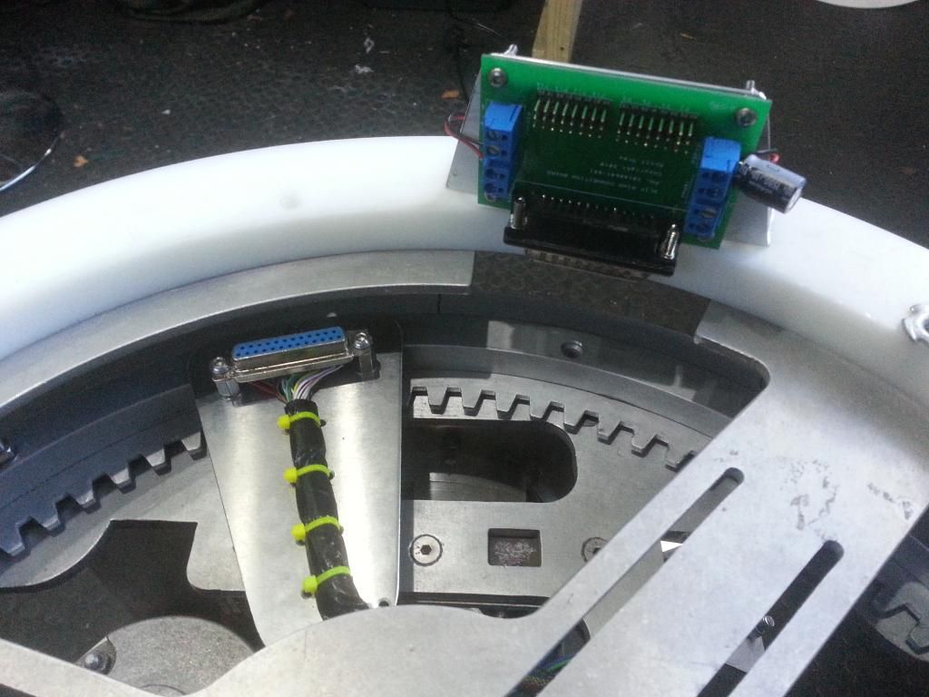
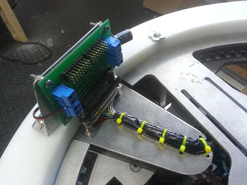
I saw a great droid at FACTs that had 2 serial connectors (9 pin i think), on a dome cross member.  These dropped into the females on the rockler.  This had 2 main advantages.  Obviously you dont need to connect the slipring by hand, but 2nd was that the dome location is set so the wiring can be better controlled.

So i had a look at my setup while i had him apart again.  After a bit of a think, and a play with a template to find the sizing and position, i decided to go for it.  I cut a small section from the dome baseplate, to allow a fixed point to be added to the rockler.  Then made an arm to carry the slip ring wire and keep it well positioned, i then fixed this to the rockler  Next i used some M4 hardware to mount the Slip ring end of the serial port connection to the arm, ready to take the PCB.

This seemed sweet, the PCB would just sit on the Derlin ring, but the connection was stiff and wouldn't quite sit right.  So removed the male surround from the pcb side and opened it up as best i could, then removed some of the side material to clear the M4 button heads and opened it a little more.  Eventually the PCB would slip on and off with minimal force, and sat tight to the connector.

Then made an Ali bracket and mounted the PCB properly to the Derlin ring.  It works really well, with the actual dome on it drops on really easily, the 3 long studs align the dome, and the arm slots in to the hole in the baseplate and connects the dome to the body.

This is going to make a big difference to the running of the droid. 


While i was doing that bit it seemed logical to rewire the UBEC.  To keep it neat and simple, i removed the metre and switch.  Then had a look at the wiring for the Adafruit, Relays and Servo/HP Arduino.  Im pretty chuffed with the results so far.  I have run out of cable ties, so will have to finish another time.  But it is a much nicer looking set-up for the changes so far.  I just hope it works, it is almost what was wired up last time, so should be ok,

I will glue the dome to the ring eventually, but will do the lifters and stuff first, so gaffa tape will hold it, on just in case, for now.


The battery was posted to Deban on Tuesday and is already on it's way back to me after it's check up. :)  Great customer service.  I also ordered a couple more T-Bars, i think mine is dodgy, and id like to be able to use the battery in either droid when Droid 2 gets a look in.

Body is still in bits, but i have a few plans for that too and im waiting for components.  But MP3 and GLI are moved and will be rewired.  Body unit wiring will need consideration, but im hoping to make things more accessible and use some dead space while freeing up more room for the gadgets.

James via a chat with Roger mentioned a new concept for connecting the legs, if that works this will be a very different droid to take apart and assemble.   Deffo looking in to that one, real potential and not seen it done before. 

Still cant quite believe im redoing and undoing a lot of the work i had just finished.  But it is all in the name of a better droid long term and testing a few more concepts and set-ups.  Too late to turn back now. 

Monday, 27 October 2014

I2C Issues Fixed and Dome rewired

Man what a long weekend!  Painful.

I thought id fixed the I2C issues, so i started a little rewiring.

I  tried to rewire the Adafruit to bypass the power on the board and use a direct supply for each relay supply, and swap from the dome 5v supply to all run on the 12v main battery.

Only to find that the Adafruit Servo driver wouldn't boot. Could I work out why?  No!  I didn't think about the library at first!  :(  So i tried to fix that and rewire at the same time, i tried all sorts.  :(  Eventually i found the issues, partly the library, partly bad connections.  Sorted them and rewired the dome using a UBEC (3a with 5A peak) to power the whole dome. Then i had crashing on the Adafruit.  Nightmare.

Also a few power issues initially, one servo not moving well and intermittent issues, so i added a capacitor to the supply and that helped sort some of the problems.  But the crashing was still happening.

After a lot of head scratching, and trying lots with the library to fix it, i realized what was happening.  The crashes were only after or part way through commands sent from the master, so the issue was passing I2C from the body.  The I2C was loosing the network and freezing the adafruit.  I had forgotten to tie the GND to the 12v into the dome, with all the problems i had overlooked it, with that re-added it is spot on. :D  So i went back to the library and reverted to an earlier attempt at the library fix.

Basically, lesson learned.  Test and fix one bug at a time, but make sure you test it fully!

The fix for the I2C was too severe initially, i needed a longer time out.  My new TWI.c file is great.  The master and ESC control is constant regardless of what happens on the I2C network, and the Adafruit works seamlessly.  :D  I will finish my rewire and run it for a week or so and post when im happy.

But the dome is now running powered by the main battery, so I have lost a lot of weight in the dome and managed to drop the dome battery.  All for £6 of ubec. :D  Here you can see my daughter boards for the power and mu UBEC fitted:


Body rewire next.  Im still not sure im doing the best thing, but im learning as i go, so having tried both i can make an informed decision.

Thursday, 23 October 2014

FACTS Fallout - MAJOR I2C Arduino Issue

If you use any I2C Arduino based elements in your droid please read on.  The way the default Arduino Wire library works may cause significant issues if power is lost to any end unit. 

FACTS was a great weekend.  Loved it.  But R2 had a few issues, and James' B4 had a few too.

Before lunch on day one, my dome battery came lose and pulled a ton of wires out.  But no harm done, re connected and added more support for the battery.  He seemed fine after that for the rest of Saturday and Sunday morning.

At one point James' droid drove on without any control!  First time id seen it do that with the master powered and relays fitted.  He said it was when the dome battery died on him.  Not something i had expected, and not what id seen in testing, but im not sure i had tested that order of issues/events. But this had to be taken very seriously and investigated ASAP.

When i got back i got straight on the case to solve it.  Testing it showed that if you boot up, then pull the power on any I2C unit, then drive dome or feet and while driving, trigger any script call, the master has then either crashed or is frozen and cant stop the ESCs.

After some analysis I found that if any device on the I2C network looses power that will freeze the master on the next I2C send.  Meaning that if driving when you trigger, it will carry on driving!!!!!  Any unit failing, or any lose wires could cause it.  Not good.  

Was this a general I2C issue?

I looked on-line for solutions and to see if i could find any others with similar issues.  All i found was Mosfet and Isolator options and level shifters, that would have added a lot of complexity to the setup, and not been ideal for my problem.  After 2 nights of research i finally bit the bullet and ordered some MOSFETs.  

But then i had a brain wave!  What if the issues were possibly code related, and could be tweaked to fix it, or at least make it safe if there is an issue.  So researching from a different start point it soon became clear that the default 'Wire' library has some pretty major issues and would wait forever for the communication to complete if there was a problem.

So i tried to use a couple of custom alternative libraries.  No joy, they wouldn't work with the higher level I2CEasyTransfer library from Bill Porter.  So i had a good read of the library files of the alternatives, and did a bit more reading.  Eventually i found that i could edit the default library, adding timeouts to stop the freezing.  All i did was to edit the 'TWI.ccp' file and add a few counters to return a 0 if the timers' max was reached to break the while loops that kept it locked.

Looks like it is sorted.  Pull the power on any I2C item and the master will not freeze on script call, so the Feet and Dome can still be controlled no matter what happens.  The network still stalls, and the first script you send is actioned if you reconnect power, but that is no bother as you will likely turn the droid off before trying to fix the issue.

I then looked at my big issue.  Starting late Sunday morning, every time i had triggered a big script the body unit would reset, and cause other niggles, pause the I2C network and was really got on my nerves!  I assumed something relating to a low 12v battery maybe? After some mucking about, i found that it was only when the Utility Arms moved that it crashed.  So i unplugged them and he seemed fine.  

The resetting of the Arduino was the puzzler, the voltage for the servos should be from the Stepdown, so them moving shouldn't have caused that issue, especially not mid move.  So i checked a few voltages and found that the 12v body DC/DC supply was reading as 8v in and 5v out, odd.  So i went round the back and there is a big red light on one of the fuses on the rigrunner!  Muppet.  Blown fuse and I guess leaking current from the pwm pins leaking trough the servos making it almost work!  Easy fix, but may look at isolating the servo power more efficiently eventually.

So R2 is working well.  But.......

While researching i kept seeing that the max output power from an Arduino as 500mA.  Knowing that the Master is now powering those big relays, it must be getting close, i will try adding a 2nd feed for the relays and retest to make sure it works as before, but leaving the draw through the master much lower.

I also found that R2 wasnt quite loud enough at FACTs, only a little, but he needed more volume.  So i have ordered a variable step up converter for the amp supply, a little more voltage should help. :D

Im debating moving to UBEC supplies for the 5v and dropping the 5v batteries and other stepdowns.  I did last 2 days on the 12v but not on the 5v ones, so it seems pointless to fight it.  I might add an alternate dome battery that i can switch to, i like the dome to be able to run alone, for when i eventually do other domes. But it might help simplify the setup theory.

Should be a safer system all round now.  Thanks to another couple of real world system issues showing themselves, and figured out, really pleased those are sorted.  I still cant believe it was that easy to address, i suppose i got lucky.  The I2C error hasn't shown it'self before in 2 years on 2 droids, but still great to see and sort it without an incident. 

 I will finish applying and testing these fixes and i have an event on the 16th, so i can do a proper test.  If it passes i will update the doc and code.

Sunday, 12 October 2014

Upgrading to 2.1 from 2.0

Upgrading from 2.0 to 2.1 should be easy, and is highly recommended.  Just replace all the mp3 files (overwrite them to make sure) and upload all the new sketches for the units you have.  Obviously swapping for your servo spots, speeds etc.

Download was updated today, it is syncing now, so check that the Master in the download is 2.1 version 4 not 3.  But I may update this week if i make any more changes.  Im playing with him till Thursday, so maybe wise to wait till then for the latest.  Link in the blog page, top right.

I have added a few things worth noting:
1.  60s after last pad interaction (stick move or script call) the feet relays turn off. Start to turn back on.
2.  Circle is now only the short scream not a random group, it also turns off LDP and Coin slot LEDs.
3.  11 More random sounds, plus the Leia snip repeated 4 time so it is more likley to be run.
4.  Music Album has been replaced.
5.  New dances and Dance bases added, and new elements added to old sketches.
6.  Fixed bugs with both dome pot and other things.
7.  Magic panel and DBC code in and tested for triggering via I2C.  DBC button triggering to follow.
8.  New Teeces sketch, this varies the timing and number of leds used.

Door relay wiring should be the same as the doc, if not swap the output of the relay, i got a bit lost on this one, unsure what was me and what was right.

Dome pot was changed to better cope with a stiffer drive.  If this causes issues i will rewrite it to make changing those values easier.

Any problems let me know. :D

PLEASE NOTE:  If using 2.0 Do NOT trigger the Luke message while driving.  It hasn't happened to me or James in over a year, but better to know about it.  The wrong delay type is used and so it may just continue to drive off for 20s.  This is fixed in 2.1.  Sorry.

I will redo the doc after FACTs.

Saturday, 11 October 2014

BHD2.1 Update and More Dancing

I finally got to do the news scripts. :D  Slow progress, but the body was a dream, that new wiring is amazing. :)  Dome is still hard work.

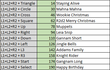
I started by looking at what i wanted to achive and the audio i had.  I had 11 clips i wanted to add as extra random sounds.  Several very cool R2 mashups from Trooper Trent on .net, and i was on a mission.  James came over and we started cutting the tunes to make shorter dances,  I also PM'd R2-X2 and borrowed his Addams Family mp3.  Superb stuff. thanks Dudes.  The Gangnam Style audio was easy because we used the start, but the some of the others wouldnt work.  So i decided just to trigger the Vegas and the Audio, then added to the Scream call to stop the Vegas as well as the track.  So at any point you can scream and stop on some.

These were the eventual additions:


Happy Birthday (2 versions), Jingle Bells and Leia snip ('Help me Obi-Wan Kenobie, you;re my only hope' quote, this one is also added as a random) is just the audio call.

Staying Alive, Mahna Mahna, Wookie and R2 Christmas and Gangnam long use the Start and Scream trick, with Gangnam Long also starting with the Gangnam Sort door dance.

The big all singing all dancing additions are the Muppets short, Addams Family, Gangnam style (both short and long start the same, but long doesnt do the dome motion).

Should be more fun with various options instead of just the good old Cantina.

First vis is the Gangnam short, with no input from me, with 2nd half being the Staying alive and me controlling the dome and doors:


This one is the Muppets and Addams Family, R2 and Wookie Christmas:


I would give it a week for me to test and upload fixes to be sure, but seems great, so the code is now on my drive, the link its to the right at the top of the blog page.  This will all run on the BHD2.0 wiring, it is just code and maybe a few tweaks to the relay setup, but im not sure that wasnt due to me wiring it wrong to start, i looks the same as the doc to me. :D

That said, after facts i will update the doc and add the new stuff and features.