
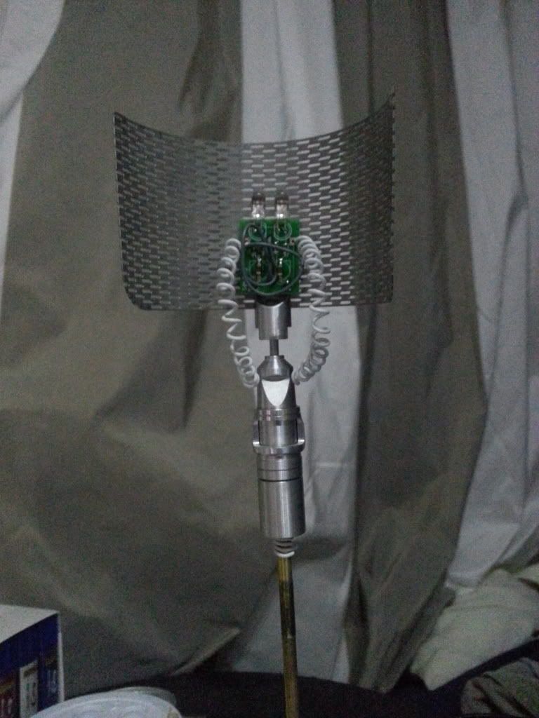
The LFS was next one the list, so i had a look at it and decided not to use the designed rotation of the top in relation to the base. My thinking was that i could then do full rotation if needed and the wires wouldn't get pulled about so would always look better. So i glued the screen on, and glued the fiddly bit to the top of the base and used a small piece of alu tube to connect them. This leaves a good size space in the centre for connecting the solid core to the flex.
The flex i have isn't right, it's a 4 core telephone handset lead, but it doesn't quite work, and i need to replace the solid core, may go with grey, black or blue instead too. So i ordered a 3.5mm headphone extension that is coiled, i hope it's about the right size. :) Waiting for that before soldering up the board. I have the option of passing the main wires down the central tube and using the flex just for the look, i don't think I'm going the aerial route, not sure yet.
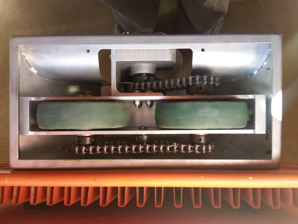
Then the leg rods. I stripped off the battery boxes and removed the ankle locks. Will leave these off till it all works, they were a bugger. :) While I had the drives off I had a look at the wheels, they were rubbing slightly, so maybe that was the cause of the static? Even if they weren't they would be costing me power. So I got some new blades for the Stanley knife and started cutting. I cut about 3-4mm off each side. Same foot print, just the edges trimmed. Seems much better, if the hubs slip i will add a few screws to hold them in position, but wont do that till it needs it.
I shortened the rods by a cut width, about 1mm, the aim was to align all the elements at the upright point (legs, feet and body). And so allow more back movement to help with balance. I stripped them out, cut them with a dremel and braced them with a steel plate.

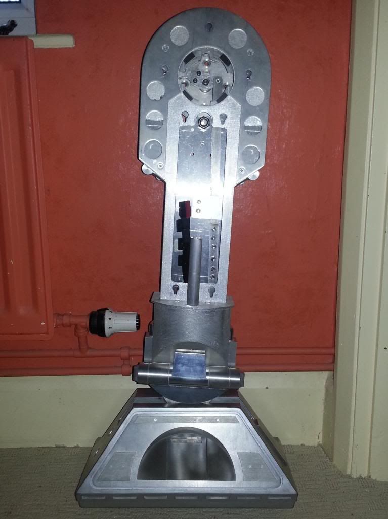
Once the ankles are sorted i will be able to strip the legs and rod setup, threadlock and final fit it. Hope that will stop it coming lose and causing issues. :)
Last night I weakened and ordered the Magic panel for the dome (the alu panel that goes red. Thinking of adding the new 3.2 PSI boards to run from that, and not the logics, that may free up enough space to do the voltage divider on the Teeces. :) Should be a nice addition. :) Will rig up the PSI boards and run them on a Nano till the Magic Panel arrives, be good to do some testing and triggering with those and maybe the HPs on their own pins. The Magic panel has 6 outs, so 3 for the HPs, and 3 for the Chain to the PSIs. :)
Started playing with the periscope control tonight too. Just a 5 button pad to trigger the 8 modes via the 3 input lines. I have the old code installed, so no off mode, but works fine. I may just edit the modes and use it this way from the same controller as the lifter. But need a breakout board to change the code on it, so that is now ordered. Will need one for the magic panel too, so will come in handy. :)
No comments:
Post a Comment