
Last night was fun. I
started by playing with resistors and making the required voltage divider for
the CBI Arduino. I used R1 as 47K and R2
as 23.7K (measured using meter). Then
made sure I was getting a 0-5v signal from it.
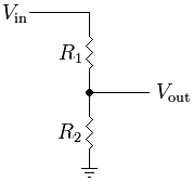
Once that was hooked up I read the analogue pin (A2) to see the fluctuation
in readings, with the conversion to the 0-15v range the output result was
fluctuating quite a lot. So I did 2
things:
1. Read the pin 4 times and took an average of the 0-1024 value given
by the pin.
2. Calculated the 0-1024 value of the min and max voltages based on
the up to 15v battery voltage, this saves the calculation having to be done on
every read.
It is really fast and smooth, and the accuracy is actually very
good, within +/- 0.05v.
So with that done I converted it into a function to generate the
0-20 (number of LEDs to show), it simply translates the measured voltage within
the min/max range and then maps that to a 0-20 value, but as the readings and range are in the 0-1024 format, there is no further calculation required other than the mapping. Then I retested the divider base code and all
looked good. Then I added it into the
main CBI code and it worked like a charm.
Just need to find the max voltage for my battery (all above will show as full), and the
empty voltage that will show as no LEDs and it will be ready to use.
I hooked it up to a couple of SLAs to test it worked and it worked fine, I
was trying to work out the voltage from the number of LEDs, I even edited the
code to get a reading on 1 battery that was outside the range I had set, turned
out that when read with a meter it was 7.2v!
So the end result is code that I add the min and max voltages as
the battery levels e.g. 11.8v and 13.7v, and the resistances e.g. 47000 or 23700 ohms as variables and the rest is done in
the code. Really pleased. Will try and add one of these to the Teeces
kit too, then I can use my bar graph option to show the charge level on the
logics, the 12v is passed via the slip ring so can be measured in the dome too.
So CBI and Body servo code is ready for the droid now, last thing to do in the code is to choose the buttons to use to trigger stuff. Mount those servos this weekend, and get it installed.
Good work! But you lost me after R2 resistor. But then got the end result :)
ReplyDelete